DAF LF45, LF55 Series. Manual — part 651
©
200515
3-33
Inspection and adjustment
EXPLANATORY NOTES ON THE MAINTENANCE ACTIVITIES
ΛΦ45/55 series
5
3.39 CHECKING THE SHOCK ABSORBERS FOR ATTACHMENT AND LEAKS
1.
Visually inspect the attachment of the shock
absorbers and for any leaks.
3.40 CHECKING THE CONDITION AND ATTACHMENTS OF SPRING LEAVES,
SPRING CLAMPS AND U-BOLTS
Checking U-bolts
1.
Visually inspect the condition and
attachment of the U-bolts.
2.
When retightening the U-bolt nuts, the
attachment nut must not be slackened first
and then tightened to the specified torque;
see "Technical data".
EXPLANATORY NOTES ON THE MAINTENANCE ACTIVITIES
3-34
©
200515
Inspection and adjustment
5
ΛΦ45/55 series
3.41 CHECKING THE HINGE POINTS AND AXLE SUSPENSION FASTENING
(AIR SUSPENSION)
Torque rod
1.
Check the attachment of the torque rod and
torque rod supports.
2.
Check the pivots of the torque rod for wear
and play.
Stabiliser bar
1.
Check the attachment of the stabiliser bar
and stabiliser bar support.
2.
Check the pivots of the stabiliser bar for wear
and play.
Ball joints three-point fixation
1.
Check the attachment of the ball joints and
three-point fixation support.
2.
Check the ball joint housing for surface
cracks.
3.
Check the dust cover for damage.

©
200515
3-35
Inspection and adjustment
EXPLANATORY NOTES ON THE MAINTENANCE ACTIVITIES
ΛΦ45/55 series
5
3.42 CHECKING THE AIR SUSPENSION BELLOWS
1.
Raise the chassis to driving height using the
remote control.
2.
Clean the air bellows using a cleaning cloth
or a soap solution, if required.
3.
Check the air bellows for cracks and
damage. If there are any cracks or damage
through which the webbing is visible, the air
bellows should be replaced.
4.
Check the air bellows, bellows seating and
air line connections for leaks.
Check that the air bellows are not chafing
against air lines, etc. when in the driving
position.
M9040
EXPLANATORY NOTES ON THE MAINTENANCE ACTIVITIES
3-36
©
200515
Inspection and adjustment
5
ΛΦ45/55 series
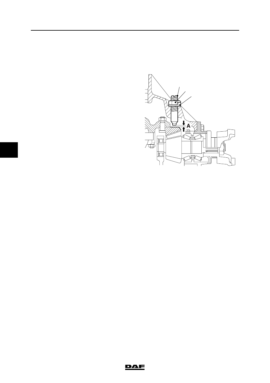
3.43 ADJUSTING THE CROWN WHEEL GUIDE BOLT
1.
Place chocks in front of the wheels and put
the vehicle on the parking brake.
2.
Loosen the circlip (1) and slacken the lock
nut (2) a few turns.
3.
Remove the adjusting screw (3) from the
differential.
4.
Remove the circlip (1).
5.
Remove the traces of sealant from the
adjusting screw and apply new sealant to the
last 4 windings of the thread, see "Technical
data".
6.
Fit the adjusting screw with a new circlip and
turn the screw against the crown wheel.
7.
Turn back the adjusting screw 1/8 of a turn to
obtain the required play A.
8.
Tighten the attachment nut to the specified
torque. See "Technical data".
Note:
Make sure that the adjusting screw does not
turn when the lock nut is tightened.
9.
Secure the lock nut by bending the circlip
lips.
A8 00 489
3
1
2
Нет комментариевНе стесняйтесь поделиться с нами вашим ценным мнением.
Текст