DAF LF45, LF55 Series. Manual — part 240
©
200508
2-1
Description of components
ZF S5-42 GEARBOX
ΛΦ45/55 series
3
4
2. DESCRIPTION OF COMPONENTS
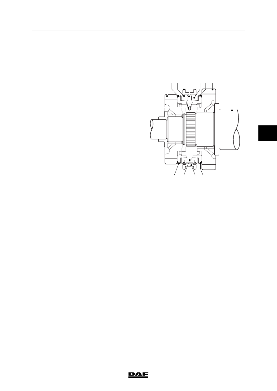
2.1 SYNCHRONISER
B-lock synchronisation
The synchroniser consists of the following parts:
1
8
2
2
7
4
7
1
6
2 3
3 2
5
1.
gear wheel
2.
selector ring
3.
synchromesh ring
4.
selector sleeve
5.
pressure spring
6.
thrust piece
7.
selector sleeve
8.
main shaft
ZF S5-42 GEARBOX
2-2
©
200508
Description of components
4
ΛΦ45/55 series
3
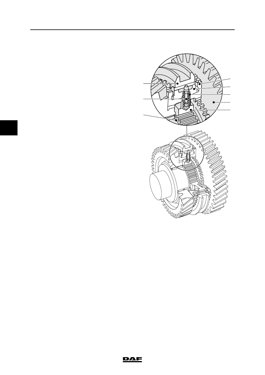
In neutral, the selector sleeve (7) is in the centre
position.
Pressure springs (5) push the thrust pieces (6)
into a wedge-shaped recess in the selector
sleeve (7).
The gear wheels (1) and corresponding selector
rings (2) move freely around the main shaft (8).
If the selector sleeve (7) is shifted to the right from
the neutral position, the synchromesh ring (3) is
pushed against the friction cone of the selector
ring (2) by the thrust pieces (6).
The difference in speed immediately turns the
synchromesh ring (3) as far as a stop on the
selector sleeve support (4), which is not in the
figure, and thus prevents further movement of
selector sleeve (7).
W 3 03 046
2
3
5
1
4
7
6
8
©
200508
2-3
Description of components
ZF S5-42 GEARBOX
ΛΦ45/55 series
3
4
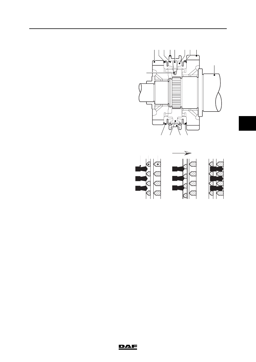
As a result of continued pressure on selector
sleeve (7) (friction), the speed of the gear (1) to
be shifted with selector ring (2) matches the
speed of the main shaft (8).
The bevelled sides of the teeth on the
synchromesh ring (3) and selector sleeve (7)
cause synchromesh ring (3) to be turned back
slightly after synchronisation.
This releases the lock and allows selector sleeve
(7) to be moved into the teeth of selector ring (2).
As a result, the relevant gear is engaged.
1
8
2
2
7
4
7
1
6
2 3
3 2
5
A
B
C
7 3
2
V301005
A.
Not connected
B.
Synchronise
C.
Connected
ZF S5-42 GEARBOX
2-4
©
200508
Description of components
4
ΛΦ45/55 series
3
Нет комментариевНе стесняйтесь поделиться с нами вашим ценным мнением.
Текст