DAF LF45, LF55 Series. Manual — part 302
©
200416
2-3
General
BE ENGINE INLET/EXHAUST SYSTEM
ΛΦ45/55 series
4
3
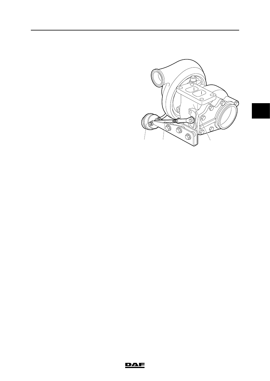
2.2 SYSTEM DESCRIPTION, TURBOCHARGER WITH WASTEGATE
To make the engine more responsive at lower
engine speeds, a turbocharger is used that
produces a better charge ratio at these speeds.
Without provision having been made for this, the
boost pressure yielded by this turbocharger
would be too high at maximum engine speeds.
Use of a wastegate prevents this.
The boost pressure is measured by a diaphragm
box (1) on the delivery side of the turbocharger.
The diaphragm is pushed back against the spring
pressure by the boost pressure. The linked
control rod (2) is also pushed back. The control
rod operates a valve in the turbine housing (3).
The valve in the turbine housing is opened when
the maximum pre-set pressure has been
reached.
When the valve is opened, some of the exhaust
gases will be discharged directly to the exhaust
pipe rather than being used to propel the turbine
rotor of the turbocharger.
i400509
3
2
1
BE ENGINE INLET/EXHAUST SYSTEM
2-4
©
200416
General
3
ΛΦ45/55 series
4
©
200416
3-1
Inspection and adjustment
BE ENGINE INLET/EXHAUST SYSTEM
ΛΦ45/55 series
4
3
3. INSPECTION AND ADJUSTMENT
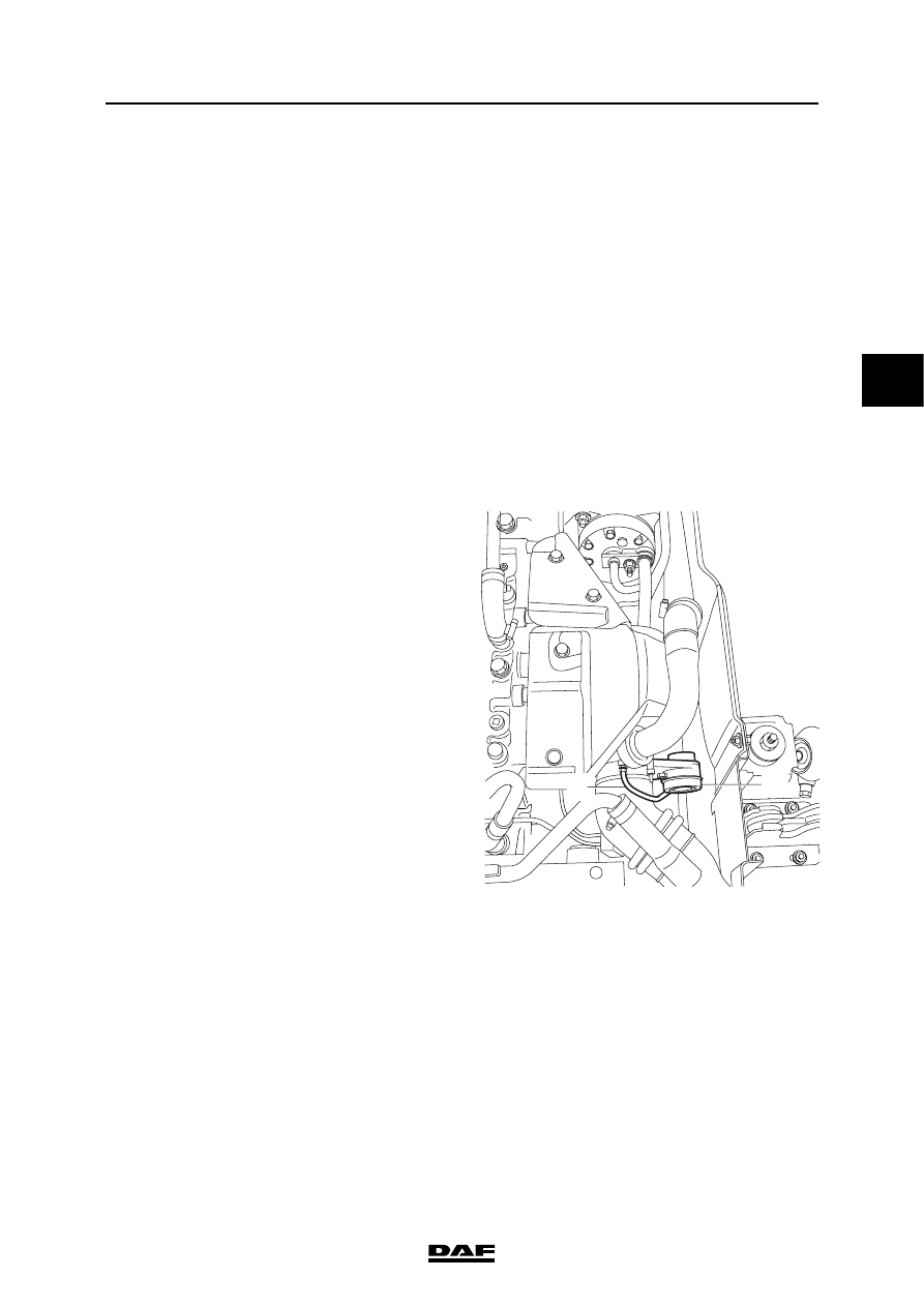
3.1 INSPECTING TURBOCHARGER WASTEGATE
Note:
Depending on the fitting position of the
turbocharger, it may be necessary to remove the
turbocharger from the engine before this
adjustment; see "Removal and installation".
Note:
The turbocharger is calibrated in the factory and
must not be re-adjusted. The length of the control
rod on the wastegate valve lever may only be
changed when assembling a new turbocharger.
After that, only an inspection of the actuating
pressure of the wastegate may be carried out. If
the result is negative, the turbocharger must be
replaced.
1.
Remove the flexible pipe (2) from the
diaphragm box (1) of the wastegate.
2.
Connect an air-pressure reducer valve to the
diaphragm box of the wastegate. Set the
reducer valve to max. 0.2 bar gauge
pressure. Connect the reducer valve to a
compressed air installation.
3.
Set the reducer valve to exactly the same
test pressure as listed in "Technical data".
4.
Check the diaphragm in the diaphragm box
for leaks by listening carefully for a hissing
sound from the diaphragm box.
5.
Check whether the control rod of the
wastegate has moved. If it has not moved,
the control rod must be loosened from the
lever. Check again whether the control rod
has moved. If is has not moved, the
diaphragm box must be replaced. If it has
moved, the wastegate valve must be made
to move freely or, if that does not help
sufficiently, the entire compressor unit must
be replaced.
6.
Remove the flexible pipe with the reducer
valve and re-connect the flexible pipe of the
compressor pump to the wastegate
diaphragm box.
2
1
i400510
BE ENGINE INLET/EXHAUST SYSTEM
3-2
©
200416
Inspection and adjustment
3
ΛΦ45/55 series
4
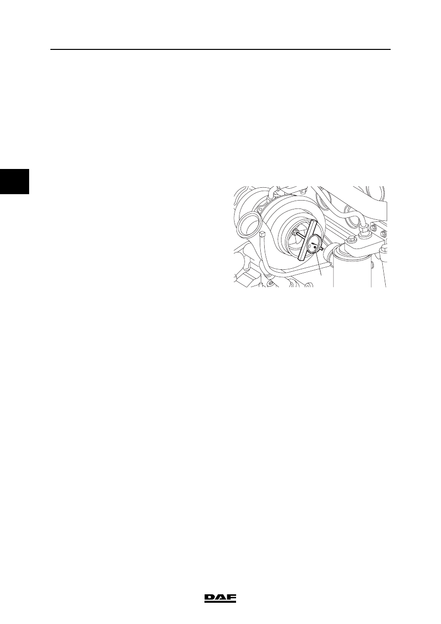
3.2 INSPECTING TURBOCHARGER AXIAL BEARING PLAY
Note:
The turbocharger axial bearing play should only
be checked when the engine is cold.
1.
Remove the exhaust pipe from the
turbocharger.
2.
Remove the charge pipes from the
turbocharger.
3.
Fit a dial gauge (1) to the charge supply
flange of the turbocharger.
4.
Push the compressor shaft away from the
dial gauge and set the gauge to zero.
5.
Push the compressor shaft to the dial gauge
and read off the axial play. Compare the
reading with the specified value; see
"Technical data". Replace the turbocharger if
necessary.
6.
Fit the charge pipes to the turbocharger.
7.
Fit the exhaust pipe to the turbocharger.
i400821
1
Нет комментариевНе стесняйтесь поделиться с нами вашим ценным мнением.
Текст