DAF LF45, LF55 Series. Manual — part 303
©
200416
3-3
Inspection and adjustment
BE ENGINE INLET/EXHAUST SYSTEM
ΛΦ45/55 series
4
3
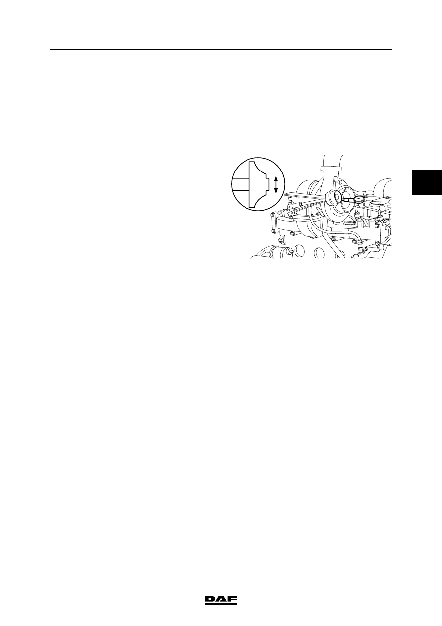
3.3 INSPECTING TURBOCHARGER RADIAL BEARING PLAY
Note:
The turbocharger radial bearing play should only
be checked when the engine is cold.
1.
Remove the turbocharger from the exhaust
manifold. See "Removal and installation".
2.
Fit a pressure gauge to the turbocharger
housing and measure the radial play.
Compare the reading with the specified
value; see "Technical data". Replace the
turbocharger if necessary.
3.
Fit the turbocharger. See "Removal and
installation".
i400650
BE ENGINE INLET/EXHAUST SYSTEM
3-4
©
200416
Inspection and adjustment
3
ΛΦ45/55 series
4
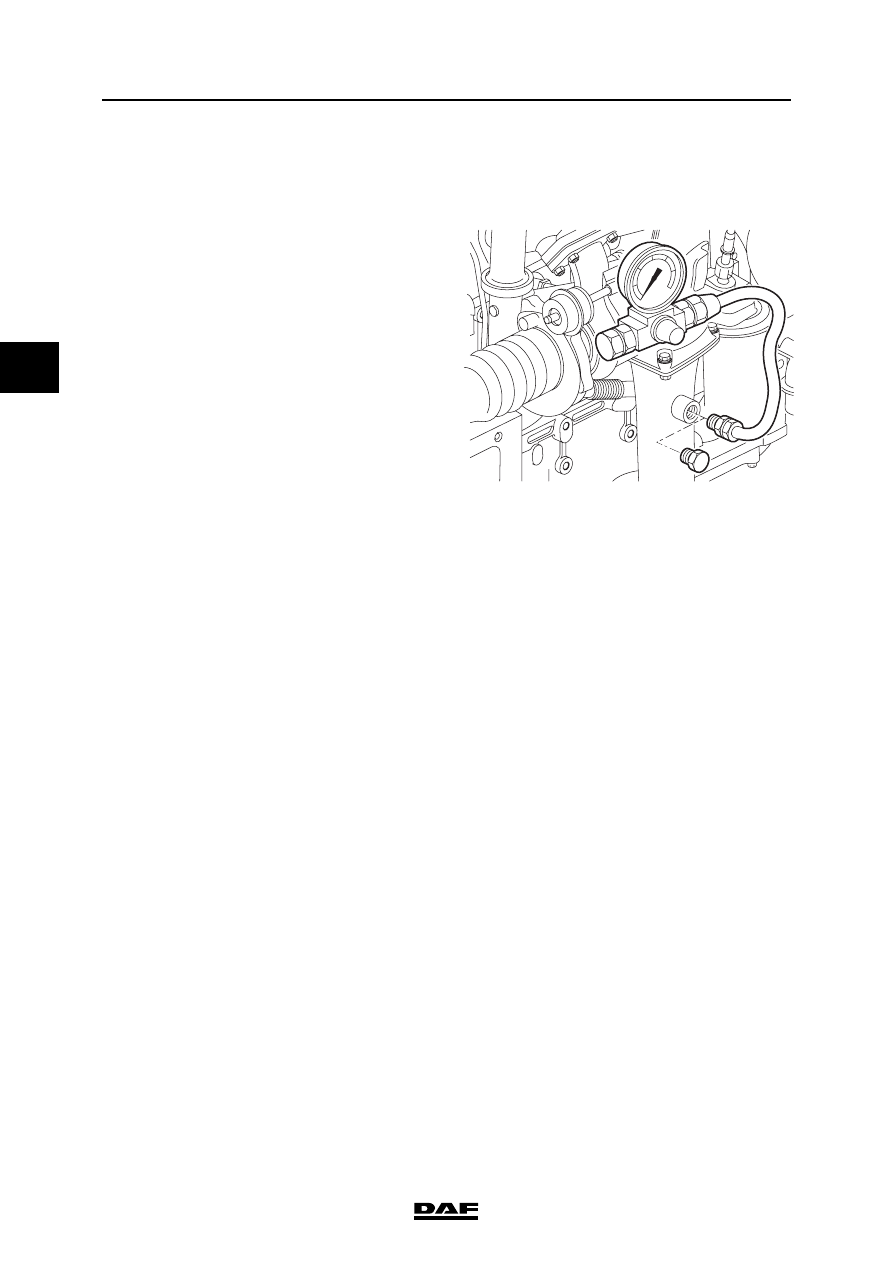
3.4 CHECKING EXHAUST GAS BACK PRESSURE
Checking exhaust gas back pressure
1.
Remove the plug from the exhaust elbow
attachment or bore a hole and install a
suitable coupling with a pipe. The first part of
the pipe must be made of metal, to withstand
the high temperatures.
Note:
Use an attenuated gauge to prevent
excessive shaking of the gauge needle.
2.
Connect a pressure gauge to the pipe, with a
range of at least 0.1 - 0.2 bar (10 - 20 kPa).
Note:
The engine brake must not be used during
measurements. This is to protect the
pressure gauge.
3.
Measure the exhaust gas back pressure at
full-load engine speed and compare the
measurements to the specified value. See
"Technical data". Check the exhaust system
if the exhaust gas back pressure is too high.
4.
Remove the pressure gauge and the
coupling and fit the plug.
i400513

©
200416
3-5
Inspection and adjustment
BE ENGINE INLET/EXHAUST SYSTEM
ΛΦ45/55 series
4
3
3.5 INSPECTION AND PRESSURE-TESTING, AIR INLET SYSTEM
When pressure-testing the air inlet
system, the plugs may spring off if
they are not properly secured. It is
therefore important to check the
attachment of the plugs before
pressure-testing and keep people
away from the area.
1.
Check the condition and mounting of the air
inlet channels/pipes of the air intake system.
Note:
In case of doubt as to the proper sealing of
the air inlet system, which is indicated by the
following:
- loss of power
- high fuel consumption
- unusual noises
- lit engine fault symbol on the instrument
panel, ???carry out a pressure test to check
the air inlet system for leakage.
2.
Remove the right-hand and rear engine
encapsulations.
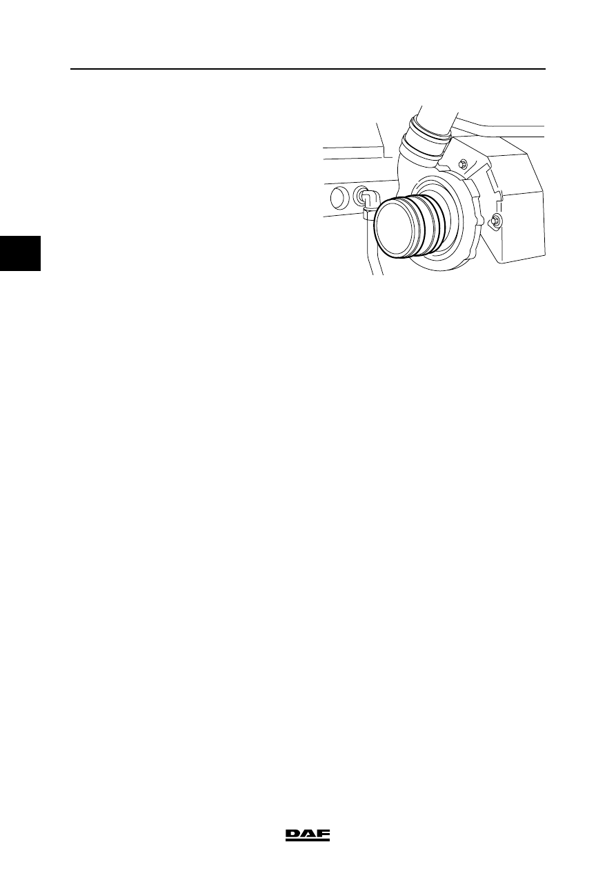
3.
Loosen the inlet hose between the air cooler
and the inlet manifold at the inlet manifold
side.
4.
Fit the special tool (DAF no. 1453171) in the
hose.
}
A
i400856
BE ENGINE INLET/EXHAUST SYSTEM
3-6
©
200416
Inspection and adjustment
3
ΛΦ45/55 series
4
5.
Loosen the plastic pipe between the air filter
housing and the rubber suction hose on the
turbocharger.
6.
Install special tool (DAF no. 1453172) in the
rubber intake port on the turbocharger.
7.
Connect an air pipe with reducer valve to the
sealing cap (A) and charge the system to
approx. 1 bar.
8.
Use a soapy solution to check the whole inlet
system for air leaks. Also check whether the
pressure gauge of the reducer valve drops.
9.
Fit the loosened hoses of the inlet system
and the engine encapsulation.
i 400376
Нет комментариевНе стесняйтесь поделиться с нами вашим ценным мнением.
Текст