DAF LF45, LF55 Series. Manual — part 230

©
200508
2-1
Inspection and adjustment
MECHANICAL GEARBOX CONTROL
ΛΦ45/55 series
3
2
2. INSPECTION AND ADJUSTMENT
2.1 INSPECTING AND ADJUSTING OPERATING MECHANISM,
2 ADJUSTMENT OPTIONS
Inspecting operating mechanism,
2 adjustment options
1.
Push the control against the spring pressure
to check whether it can move freely in
neutral.
2.
Check that all gears can be engaged without
parts coming into contact with each other.
3.
During a test drive, check that the gear
remains engaged under changing
conditions.
Adjusting the gearbox control,
2 adjustment options
1.
Remove the switch button (see "Removal
and installation").
2.
Remove the gaiter (see "Removal and
installation").
3.
Loosen the lock nuts (3) of the gearbox lever.
4.
Loosen the lock nuts (2) of the torque rod on
both sides.
5.
Remove attachment nut (1) from the torque
rod on control rod side.
2
1
3
V3 00 575
MECHANICAL GEARBOX CONTROL
2-2
©
200508
Inspection and adjustment
2
ΛΦ45/55 series
3
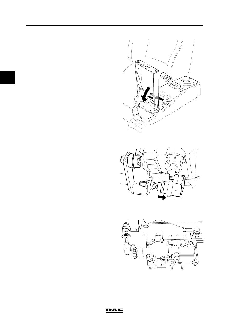
6.
Fix the gear lever by fitting the special tool
(DAF no. 1329488) over the gear lever and
inserting the end of the gear lever through
the appropriate opening.
7.
Fit the special tool (DAF no. 1453143)
between the ball joint (1) and the arm (2).
Centre the ball joint (1) by pressing it against
the shoulder of the special tool (A).
Note:
On the special tool (A) (DAF no. 1453143) it
is shown which side of the tool must be used
for LHD vehicles and which side for RHD
vehicles.
8.
Hand-tighten the lock nuts (3) of the gearbox
lever without moving the control rod.
9.
Tighten the lock nuts (3) on the gearbox lever
to the specified torque without moving the
control rod. See "Technical data".
10. Adjust the length of the torque rod in such a
way that it can be positioned in the control
rod without tension. Tighten the attachment
nut (1) to the specified torque. See
"Technical data".
V3 00 580
V3 00 840
RHD
1
A
2
2
1
3
V3 00 575

©
200508
2-3
Inspection and adjustment
MECHANICAL GEARBOX CONTROL
ΛΦ45/55 series
3
2
11. Tighten the lock nuts (2) on the torque rod to
the specified torque without moving the
torque rod. See "Technical data".
12. Remove the special tool from the ball joint.
13. Clean part (A) of the control rod and remove
any grease.
14. Apply the specified lubricant lightly to section
(B) of the control rod. See "Technical data".
15. Remove the special tool and fit the gaiter.
See "Removal and installation".
16. Fit the switch button. See "Removal and
installation".
V3 00 746
B
A

MECHANICAL GEARBOX CONTROL
2-4
©
200508
Inspection and adjustment
2
ΛΦ45/55 series
3
2.2 INSPECTING AND ADJUSTING OPERATING MECHANISM,
4 ADJUSTMENT OPTIONS
Inspecting operating mechanism,
4 adjustment options
1.
Push the control against the spring pressure
to check whether it can move freely in
neutral.
2.
Check that all gears can be engaged without
parts coming into contact with each other.
3.
During a test drive, check that the gear
remains engaged under changing
conditions.
Adjusting the gearbox control,
4 adjustment options
1.
Remove the retaining clip and disassemble
the control rods underneath the cab.
2.
Measure the length of the control rod and
compare the measured reading (A) with the
specified reading. See "Technical data".
3.
If necessary, adjust the length.
4.
Clean part (B) of the control rod and remove
any grease.
5.
Apply the specified lubricant lightly to section
(C) of the control rod. See "Technical data".
6.
Measure the length (B) of the control rod ball
joint behind the cab and compare the
measured reading with the specified reading.
See "Technical data".
7.
If necessary, adjust the length of the ball
joint.
8.
Remove the switch button (see "Removal
and installation").
9.
Remove the gaiter (see "Removal and
installation").
V3 00 745
A
C
B
V3 00 564
B
Нет комментариевНе стесняйтесь поделиться с нами вашим ценным мнением.
Текст