DAF LF45, LF55 Series. Manual — part 231
©
200508
2-5
Inspection and adjustment
MECHANICAL GEARBOX CONTROL
ΛΦ45/55 series
3
2
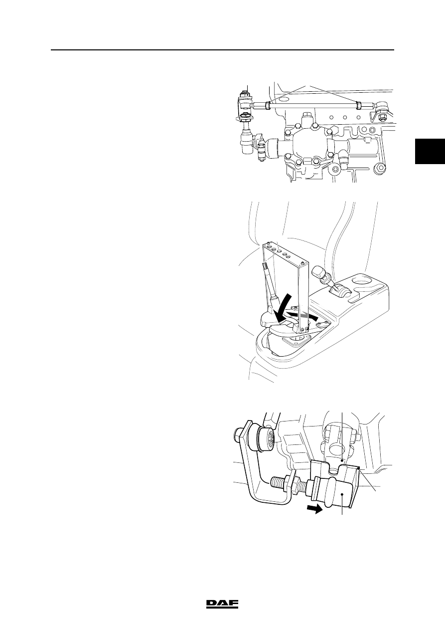
10. Loosen the lock nuts (3) of the gearbox lever.
11. Loosen the lock nuts (2) of the torque rod on
both sides.
12. Remove attachment nut (1) from the torque
rod on control rod side.
13. Fix the gear lever by fitting the special tool
(DAF no. 1329488) over the gear lever and
inserting the end of the gear lever through
the appropriate opening.
14. Fit the special tool (DAF no. 1453143)
between the ball joint (1) and the arm (2).
Centre the ball joint (1) by pressing it against
the shoulder of the special tool (A).
Note:
On the special tool (A) (DAF no. 1453143) it
is shown which side of the tool must be used
for LHD vehicles and which side for RHD
vehicles.
2
1
3
V3 00 575
V3 00 580
V3 00 840
RHD
1
A
2
MECHANICAL GEARBOX CONTROL
2-6
©
200508
Inspection and adjustment
2
ΛΦ45/55 series
3
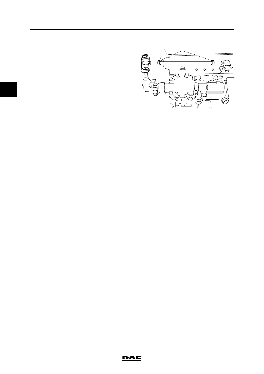
15. Hand-tighten the lock nuts (3) of the gearbox
lever without moving the control rod.
16. Tighten the lock nuts (3) on the gearbox lever
to the specified torque without moving the
control rod. See "Technical data".
17. Adjust the length of the torque rod in such a
way that it can be positioned in the control
rod without tension. Tighten the attachment
nut (1) to the specified torque. See
"Technical data".
18. Tighten the lock nuts (2) on the torque rod to
the specified torque without moving the
torque rod. See "Technical data".
19. Remove the special tool from the ball joint.
20. Remove the special tool and fit the gaiter.
See "Removal and installation".
21. Fit the switch button. See "Removal and
installation".
2
1
3
V3 00 575
©
200508
3-1
Removal and installation
MECHANICAL GEARBOX CONTROL
ΛΦ45/55 series
3
2
3. REMOVAL AND INSTALLATION
3.1 REMOVING AND INSTALLING SWITCH BUTTON
Removing ZF gearbox switch button
1.
Turn the switch button anti-clockwise away
from the gear lever.
Installing ZF gearbox gear lever
1.
Apply locking compound to the gear lever
wire. See "Technical data".
2.
Turn the switch button clockwise onto the
gear lever.
3.
Position the switch button so that it
corresponds to the gear-shift movement.
Removing Eaton gearbox switch button
1.
Remove the cover plate and the gear-
change pattern from the top of the switch
button.
2.
Remove the attachment nut from the switch
button.
3.
Remove the switch button.
4.
Remove the gaiter.
5.
Position the gear lever as far forward as
possible and remove the range-change
switch.
Installing Eaton gearbox switch button
1.
Position the gear lever as far forward as
possible and fit the range-change switch
over the gear lever.
2.
Position the air pipes so that they cannot get
trapped between the gear lever and the cab.
3.
Fit the gaiter.
4.
Apply locking compound to the gear lever
wire. See "Technical data".
5.
Fit the switch button onto the gear lever and
tighten the attachment nut to the specified
torque. See "Technical data".
6.
Fit the cover plate.
MECHANICAL GEARBOX CONTROL
3-2
©
200508
Removal and installation
2
ΛΦ45/55 series
3
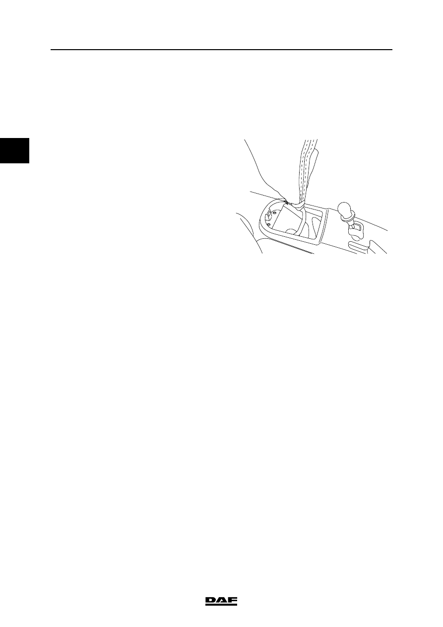
3.2 REMOVING AND INSTALLING GAITER
Removing gaiter
1.
Remove the switch button.
2.
Disconnect the underside of the gaiter.
3.
Pull the gaiter over the switch button and
remove the clamping strap (1).
4.
Remove the gaiter.
Installing gaiter
1.
Fit a new clamping strap on the inside of the
gaiter.
2.
Fit the top of the gaiter inside out over the
gear lever and tighten the clamping strap (1).
3.
Pull the entire gaiter over the gear lever.
4.
Tighten the underside of the gaiter.
V3 00 578
1
Нет комментариевНе стесняйтесь поделиться с нами вашим ценным мнением.
Текст