DAF LF45, LF55 Series. Manual — part 274
©
200508
3-1
Removal and installation
PROP SHAFTS
ΛΦ45/55 series
3
10
3. REMOVAL AND INSTALLATION
3.1 REMOVING AND INSTALLING SPICER PROP SHAFT/INTERMEDIATE SHAFT
ASSEMBLY
Removing prop shaft/intermediate shaft
assembly
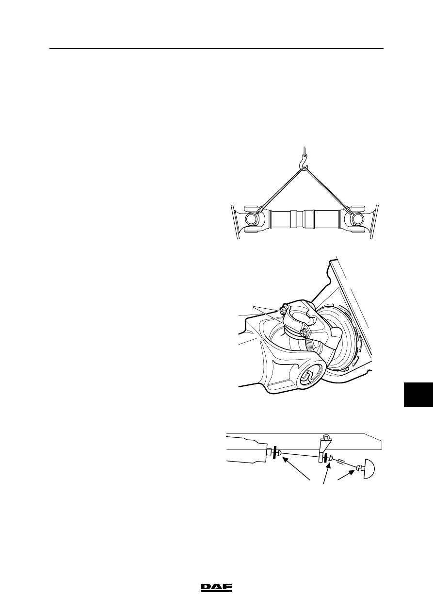
Note:
When removing one of the shafts in vehicles with
multiple shafts (prop shaft and intermediate
shafts), the other shaft must be tied to the chassis
or intermediate beam in such a way that it does
not obstruct the various operations. Always
transport and store shafts horizontally to avoid
damage and subsequent imbalance. Support the
shaft in at least two places. If possible, hang the
shaft in a hoist, using two sturdy ropes.
1.
Remove the attachment bolts from the
flanges and/or clamping pieces (1), and
carefully lower the shaft to the ground.
2.
Now remove the shaft from under the
vehicle.
Installing prop shaft/intermediate shaft
assembly
Note:
After repairs have been carried out or a shaft has
been replaced, the forks of all shafts must be
aligned.
1.
Fit the shaft under the vehicle. Use a hoist if
possible.
2.
Fit the attachment bolts. Tighten the
attachment bolts to the specified torque. See
"Technical data".
W 3 06 016
V3 00 377
1
=
=
W 3 06 019
PROP SHAFTS
3-2
©
200508
Removal and installation
10
ΛΦ45/55 series
3
3.2 REMOVAL AND INSTALLATION, PROP SHAFT/INTERMEDIATE SHAFT
ASSEMBLY
Removing prop shaft/intermediate shaft
assembly
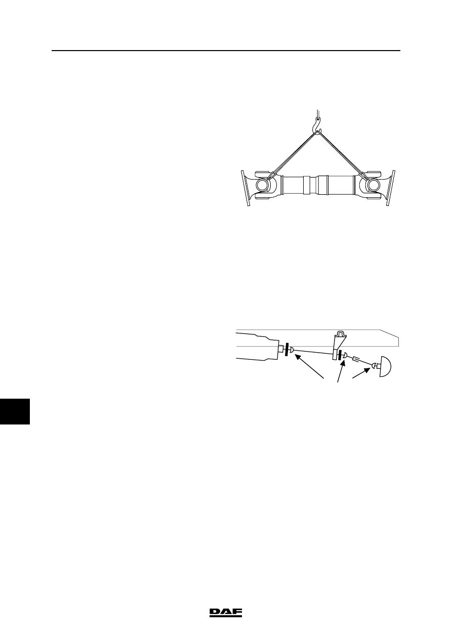
1.
When removing one of the shafts in vehicles
with multiple shafts (prop shaft and
intermediate shafts), the other shaft must be
tied to the chassis or intermediate beam in
such a way that it does not obstruct the
various activities.
Note:
Always transport and store shafts
horizontally to avoid damage and
subsequent imbalance.
Support the shaft in at least two places. If
possible, hang the shaft in a hoist, using two
sturdy ropes.
2.
Remove the attachment bolts from the
flanges and carefully lower the shaft to the
ground.
Now remove the shaft from under the
vehicle.
Installing prop shaft/intermediate shaft
assembly
Note:
After repairs have been carried out or a shaft has
been replaced, the marks on the shafts must be
opposite each other.
1.
Fit the shaft under the vehicle. Use a hoist if
possible.
2.
Tighten the attachment bolts to the specified
torque. See "Technical data".
W 3 06 016
=
=
W 3 06 019
©
200508
4-1
Demounting and mounting
PROP SHAFTS
ΛΦ45/55 series
3
10
4. DEMOUNTING AND MOUNTING
4.1 DEMOUNTING AND MOUNTING UNIVERSAL JOINT
Demounting universal joint
1.
Remove the prop shaft and/or intermediate
shaft assembly.
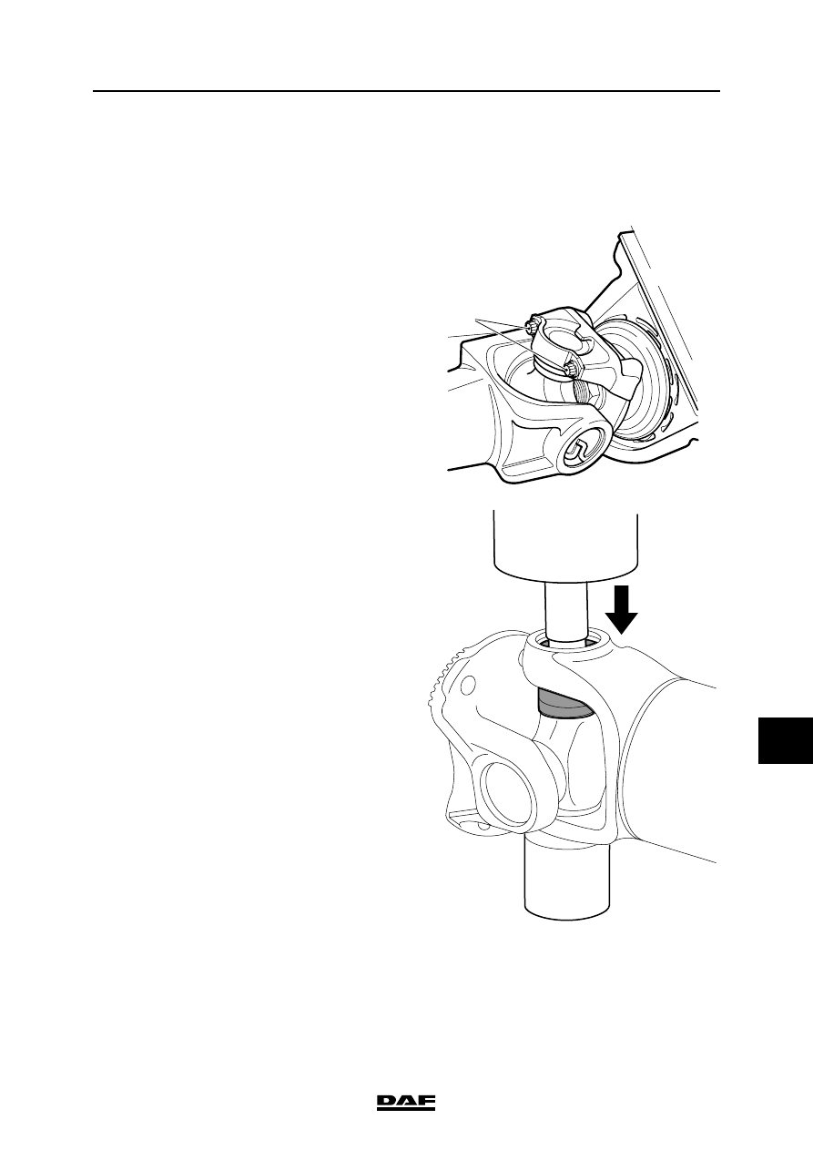
2.
Remove the circlips and the attachment bolts
of the clamping pieces (1) of the spider to be
replaced.
3.
Place the shaft on a bush underneath a
press, as shown, and press the entire spider
including bearings and drive flange down
until the spider touches the fork of the shaft.
V3 00 377
1
W306010-2
PROP SHAFTS
4-2
©
200508
Demounting and mounting
10
ΛΦ45/55 series
3
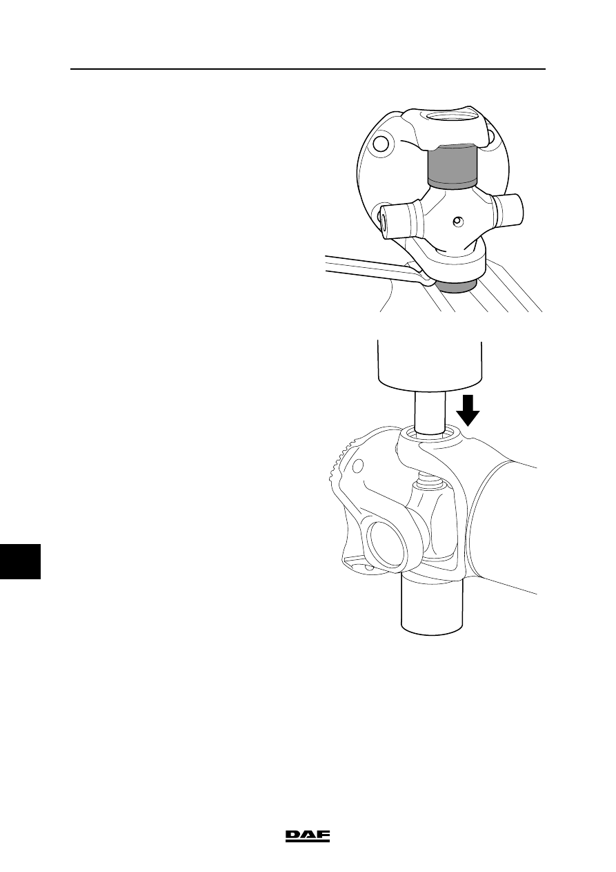
4.
Rotate the shaft 180
″ and remove the
bearing that has just been pressed out. If the
first bearing to be removed fails to come out
of the fork entirely, it can be clamped to
enable the fork to be pushed up by means of
a lever. Place the shaft back on the bush.
5.
Push the spider down again in the direction
of the shaft fork. Again, continue until the
spider touches the fork.
6.
The spider and the drive flange can now be
tipped out of the shaft fork.
7.
Place the drive flange on a bush underneath
a press and press the entire spider including
bearings and drive flange down until the
spider touches the fork of the drive flange.
8.
Rotate the drive flange 180
″ and remove the
bearing that has just been pressed out.
Place the drive flange back on the bush.
9.
Push the spider down again in the direction
of the shaft fork. Again, continue until the
spider touches the fork.
10. The spider can now be tipped out of the drive
flange fork.
Note:
When spiders are being replaced, always
replace them including their bearings.
11. Check the components to be reused for any
cracks and/or damage.
Mounting universal joint
Note:
After mounting, it must be possible to move
the drive flanges and spiders by hand. When
mounting the spider, Seeger rings of the
same thickness must be used.
W306012-2
W306011-2
Нет комментариевНе стесняйтесь поделиться с нами вашим ценным мнением.
Текст