DAF LF45, LF55 Series. Manual — part 487
0
7
LF45/55 series
152N front axle
TECHNICAL DATA
6-7
6.2 TIGHTENING TORQUES
The tightening torques stated in this section are
different from the standard tightening torques
included in the overview of standard tightening
torques. Any other threaded connections that
are not specified must therefore be tightened to
the tightening torque stated in the overview of
standard tightening torques.
When attachment bolts and nuts are to be
replaced, it is important - unless stated
otherwise - that these bolts and nuts are of
exactly the same length and property class as
the ones removed
.
ᓻ 200322
7
TECHNICAL DATA
152N front axle
LF45/55 series
6-8
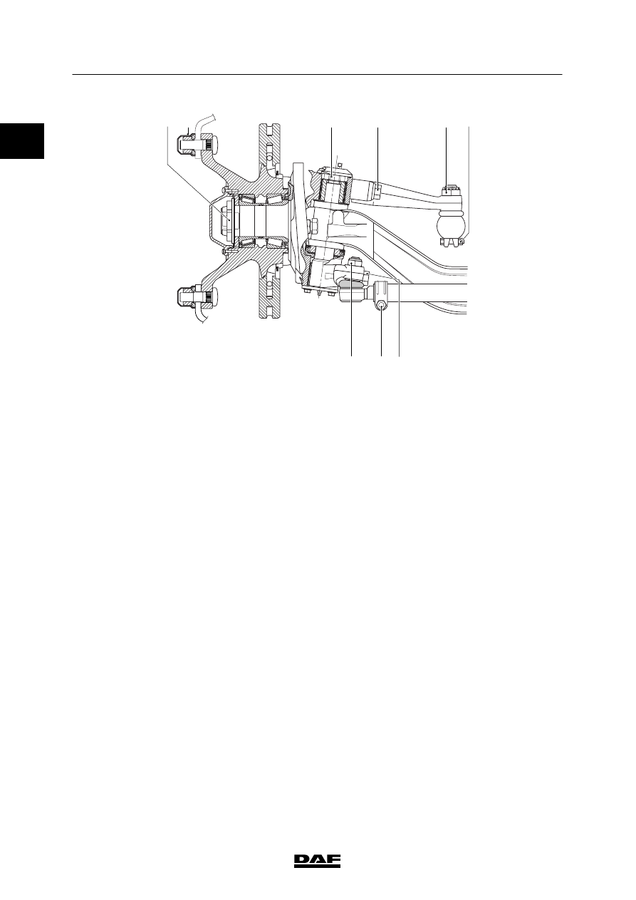
A B
F
G
H
C
I
D
E
S7 00 883
A.
Hub nut of wheel hub unit
-
1
st
phase
400 Nm
(1)
-
2
nd
phase
turn the hub through 10 rotations
(2)
-
3
rd
phase
450 Nm
-
4
th
phase
turn the hub through 10 rotations
(2)
-
5
th
phase
950 Nm
B.
Wheel nut
700 Nm
(3)
C.
King-pin nut
595 Nm
(4)
D.
Steering-rod arm attachment bolt
500 Nm + 90
_ angular displacement
(5)
E.
Steering rod castle nut
220 Nm
(6)
F.
Attachment bolt, steering-rod clamping
bracket
90 Nm
(1)
G.
M20 attachment nut, track rod
225 Nm
(7)
H.
M12 attachment bolt, track rod clamping
bracket
80 Nm
(1)
I.
Track rod arm attachment bolt
500 Nm + 90
_ angular displacement
(5)
(1)
Fit new nut.
(2)
Rotate the hub at a speed of approx. 40 rpm.
(3)
Retighten after 100 km. If new wheel bolts have been
fitted, the wheels need additional retightening after
500 km.
(4)
Apply Loctite 243 to the nut.
(5)
Fit new attachment bolt. Apply Loctite 243 to the
attachment bolt.
(6)
Tighten until the split pin fits (max. 60
_).
(7)
Check the screw thread of the ball end for damage. Fit
new self-locking nut. Apply Loctite 243 to the nut.
0
ᓻ 200322
0
7
LF45/55 series
Steered trailing swivel axle
TECHNICAL DATA
7-1
7. STEERED TRAILING SWIVEL AXLE
7.1 GENERAL
Axle journal
Anti-corrosion agent
Gleitmo 805
Wheel speed sensor
Anti-corrosion agent
Molykote P37
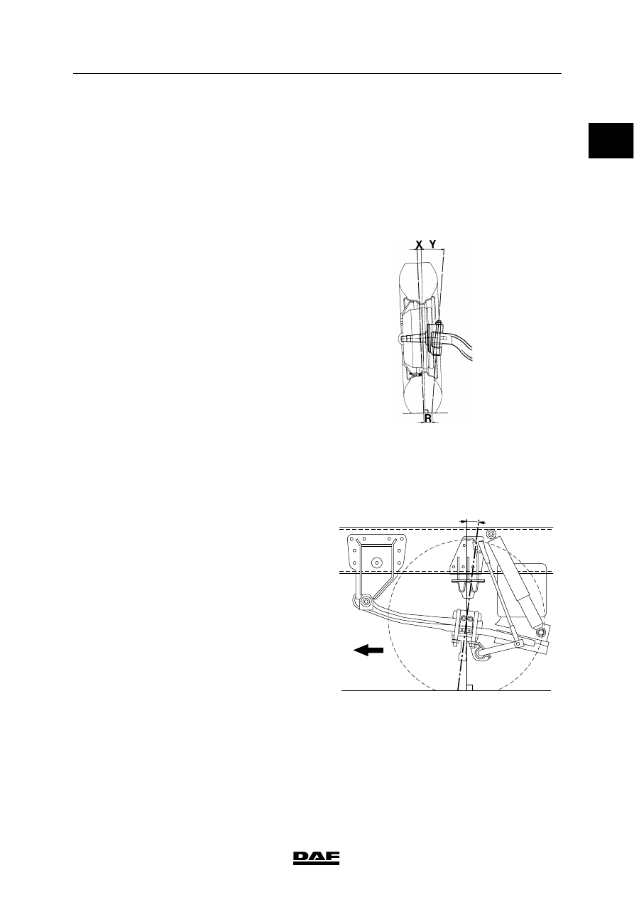
Camber angle and kingpin inclination (KPI)
Camber angle (X) on an
unloaded axle
0
_30′
King-pin inclination (Y)
7
_15′
S7 00 129
Wheel deflection
Maximum inner wheel
deflection
20
_
Caster
Z = caster
-
unloaded
3
_
-
loaded
5.4
_
Z
S7 00 835
ᓻ 200322
7
TECHNICAL DATA
Steered trailing swivel axle
LF45/55 series
7-2
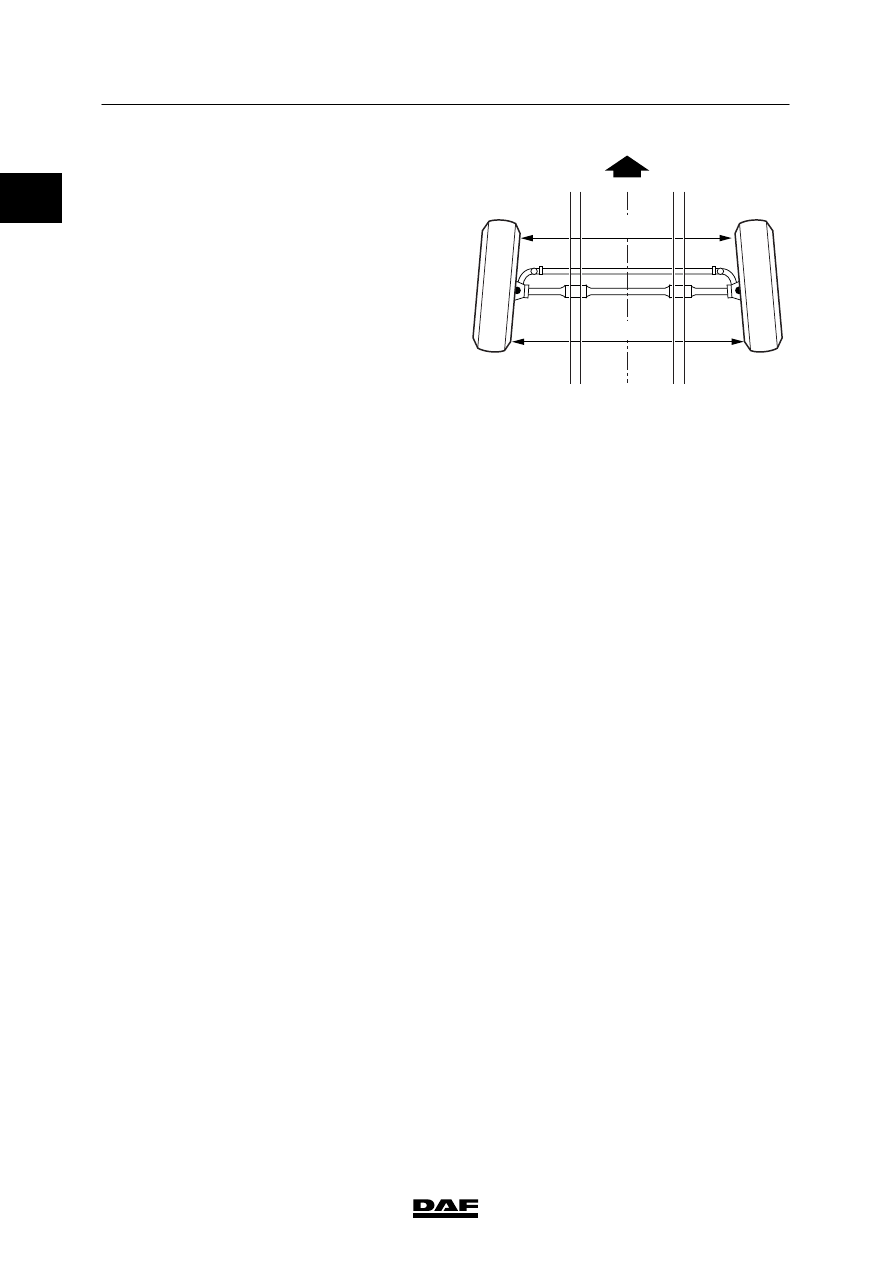
Toe
Measured at the side walls of the tyre (B -- A)
in unloaded condition
Toe-in
0 - 1.6 mm
S7 00 833
A
B
Steering ball joints
Axial play
max. 1.5 mm
King pin
Pressing force
150 kN
Steering cylinder
Length, retracted
982
ᐔ 5 mm
Length, centre position
1092
ᐔ 5 mm
Length, extended
1202
ᐔ 5 mm
0
ᓻ 200322
Нет комментариевНе стесняйтесь поделиться с нами вашим ценным мнением.
Текст