DAF LF45, LF55 Series. Manual — part 318
©
200416
5-7
Removal and installation
CE ENGINE FUEL SYSTEM
ΛΦ45/55 series
4
5
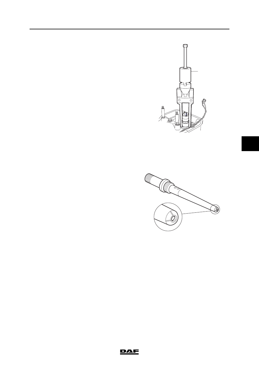
8.
Fit the injector puller (1). This is the special
tool (DAF no. 0192496). Carefully pull the
injector vertically out of the cylinder head.
9.
Remove the copper washer from the injector
hole and plug the hole immediately.
Installing the injector
The following guidelines must be adhered to:
-
If the injector is defective, both the injector
and the fuel supply pipe must be replaced.
-
If the fuel supply pipe is defective and in
addition the sealing surface with the injector
is damaged, both the injector and the fuel
supply pipe must be replaced.
-
If the fuel supply pipe is defective and the
sealing surface with the injector is not
damaged, the fuel supply pipe must be
replaced but the injector can be reused.
1.
Clean the injector if it has already been used.
See "Cleaning".
2.
Clean the injector hole in the cylinder head.
The metal surface of the hole must not be
touched.
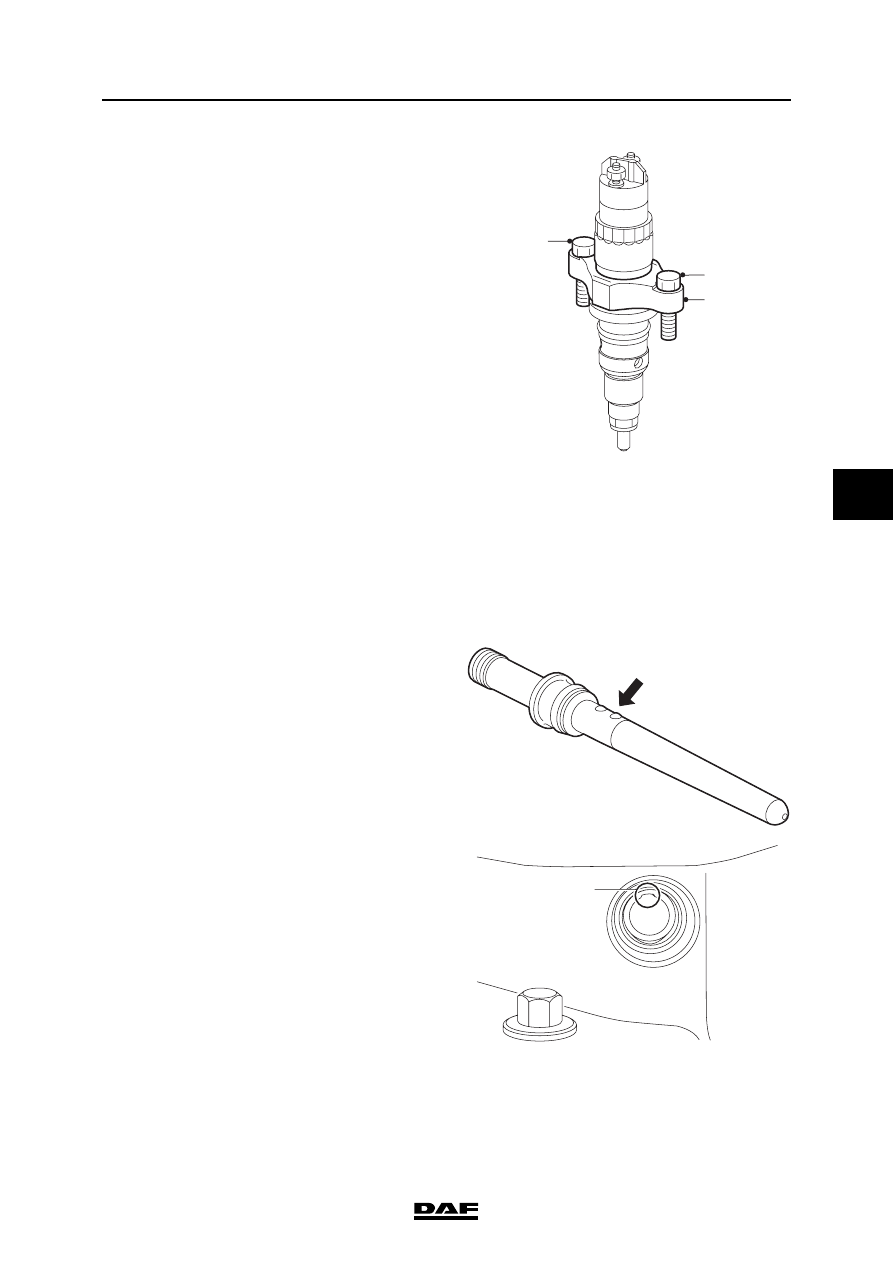
3.
Check the fuel supply pipe for damage and
signs of leakage.
Leakage in the fuel supply pipe can be
recognised by erosion tracks (lines) on the
nose of the supply pipe. If necessary or if in
doubt, replace the fuel supply pipe.
4.
Fit a new O-ring on the fuel supply pipe.
5.
Check that the injector fuel connection is not
leaking.
Leakage in the injector fuel connection can
be recognised by erosion tracks (lines) in the
socket of the fuel connection . If necessary or
if in doubt, replace the injector.
1
i400804
i400776

CE ENGINE FUEL SYSTEM
5-8
©
200416
Removal and installation
5
ΛΦ45/55 series
4
6.
Fit a new copper washer on the injector.
Measure the length of the injector nozzle (A)
without fitted washer in order to determine
which washer must be used. Fit the correct
washer; see "Technical data".
Note:
A wrong washer will cause an incorrect
alignment between the fuel supply pipe and
the injector. This will lead to internal fuel
leaks that will in turn cause loss of power
and/or engine damage.
7.
Fit a new O-ring on the injector.
Note:
This O-ring should prevent returning fuel (1.2
- 2.0 bar) flowing via the top of the cylinder
head to the oil sump and thinning the oil.
8.
Apply a thin layer of clean engine oil to the O-
ring of the injector.
9.
Fit the injector with the copper washer. First
press the injector into the hole as far as
possible until a higher resistance can clearly
be felt.
Note:
The injector must only be fitted one way. If it
is fitted incorrectly, serious damage can
ensue. The rounded side (2) of the injector
clamping bracket (1) must point to the inlet
side of the engine (A).
i400693
A
i400805
1
2
A
©
200416
5-9
Removal and installation
CE ENGINE FUEL SYSTEM
ΛΦ45/55 series
4
5
10. Fit the attachment bolts (1) in the injector
clamping bracket (2) to secure the injector.
Tighten the attachment bolts alternately to a
torque of 2 Nm.
Note:
Pay special attention to the tightening of the
attachment bolts (1). The tightening must be
carried out alternately; ensure that the
injector clamping bracket (2) is not fitted at
an angle.
11. Apply a thin layer of clean engine oil to the O-
ring of the fuel supply pipe, the screw thread
of the nut and the contact surface of the nut
with the fuel supply pipe.
12. Check the bore of the fuel supply pipe for
foreign matter and damage. Also check
whether the supply bore in the injector is
correctly positioned for the bore, because it
is possible to mount the injector turned
through 180
, so that the fuel supply port is
on the other side.
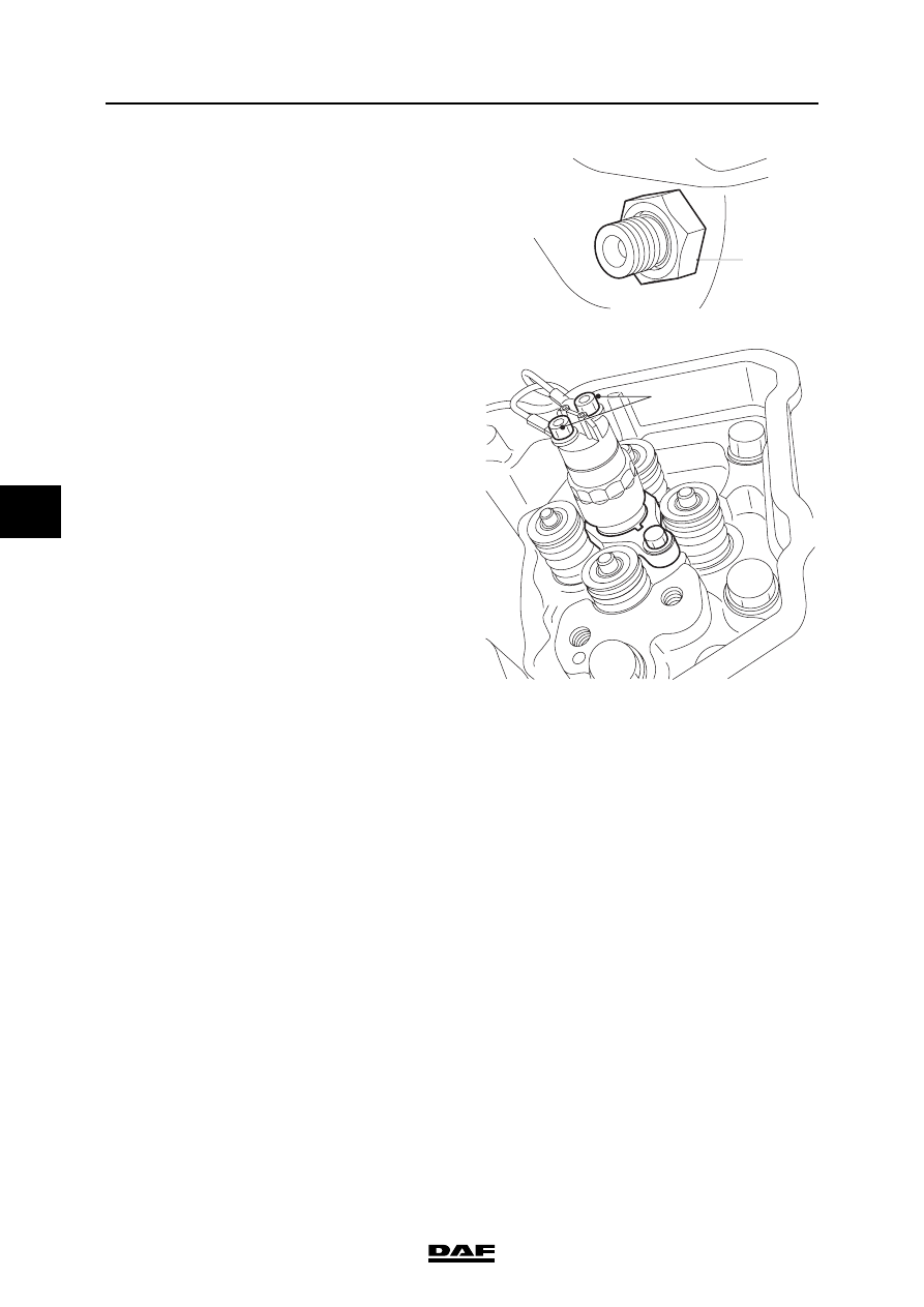
13. Fit the fuel supply pipe. Press the fuel supply
pipe as far as possible into the bore, with the
ball pointing upwards. Ensure that the O-ring
is not damaged in this process.
Note:
The fuel supply pipe has one or two positioning
balls. The fuel supply pipe can only be installed
with the ball(s) on top, as the bore in the cylinder
head has a groove (1) at the top.
i400806
1
1
2
i400790
1
i400807
CE ENGINE FUEL SYSTEM
5-10
©
200416
Removal and installation
5
ΛΦ45/55 series
4
14. Fit the nut (1). Tighten the nut to a torque of
15 Nm.
15. Tighten the injector attachment bolts to the
specified torque; see "Technical data".
16. Tighten the fuel supply pipe nut to the
specified torque; see "Technical data".
17. Connect the injector wiring. Tighten the
attachment bolts (1) to the specified torque.
See "Technical data".
18. Fit the exhaust valve rockers.
19. Adjust the clearance of the exhaust valves.
20. Fit the valve cover.
21. If the fuel rail was removed, re-fit it.
22. Fit the injector pipe.
23. Fit the fuel return overflow valve to the
cylinder head. For the specified tightening
torque, see "Technical data".
24. Connect the return pipe to this valve.
25. Start the engine to bleed the high-pressure
section of the fuel system and inspect the
fuel system for leaks.
1
i400486
i400808
1
Нет комментариевНе стесняйтесь поделиться с нами вашим ценным мнением.
Текст