DAF LF45, LF55 Series. Manual — part 316
©
200416
4-7
Inspection and adjustment
CE ENGINE FUEL SYSTEM
ΛΦ45/55 series
4
5
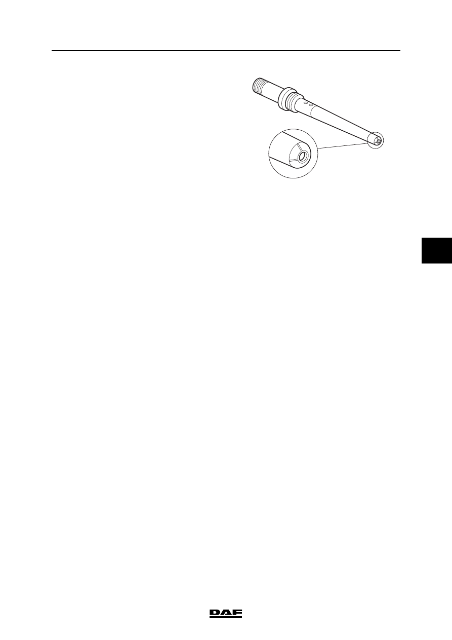
7.
Check the fuel supply pipe for damage and
signs of leakage.
Leakage in the fuel supply pipe can be
recognised by erosion tracks (lines) on the
nose of the supply pipe. If necessary or if in
doubt, replace the fuel supply pipe.
8.
Check that the injector fuel connection is not
leaking.
Leakage in the injector fuel connection can
be recognised by erosion tracks (lines) in the
socket of the fuel connection . If necessary or
if in doubt, replace the injector.
Note:
If fuel has been found in the lubricating oil,
extra attention must be paid to the O-rings of
the injectors, as these have most probably
been damaged by increased pressure in the
return circuit as a result of an internal leak.
Note:
The following guidelines must be adhered to:
-
If the injector is defective, both the injector
and the fuel supply pipe must be replaced.
-
If the fuel supply pipe is defective and in
addition the sealing surface with the injector
is damaged, both the injector and the fuel
supply pipe must be replaced.
-
If the fuel supply pipe is defective and the
sealing surface with the injector is not
damaged, the fuel supply pipe must be
replaced but the injector can be reused.
9.
Fit the injector and fuel supply pipe. See
"Removal and installation".
10. Again inspect for internal fuel leaks to check
that there is no leakage.
i400776
CE ENGINE FUEL SYSTEM
4-8
©
200416
Inspection and adjustment
5
ΛΦ45/55 series
4
©
200416
5-1
Removal and installation
CE ENGINE FUEL SYSTEM
ΛΦ45/55 series
4
5
5. REMOVAL AND INSTALLATION
5.1 REMOVAL AND INSTALLATION, INJECTOR PIPE
Never bend injector pipes as they
may kink or crack.
The injector pipes form part of the
high-pressure section of the fuel
system. When the unions are
unscrewed, fuel under high pressure
may escape. Take measures to
prevent fire and injury. Collect the
escaping fuel in a suitable container.
Dirt in the fuel system can lead to
significant damage to parts of the
system. Prevent this by cleaning the
parts before disassembly and then
sealing all open connections.
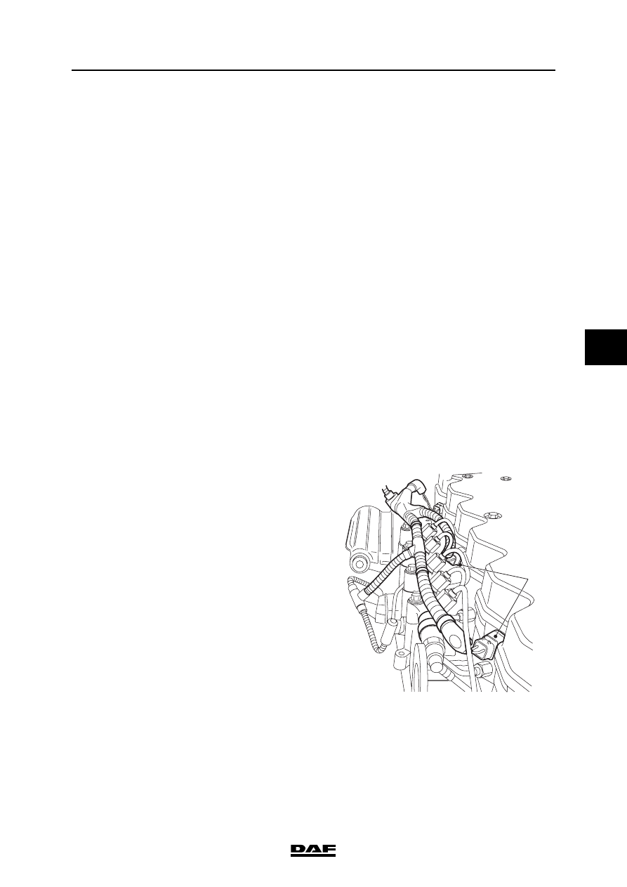
Note:
Codes (1) are stamped in the injector pipe unions
to enable correct positioning. The first figure is
the number of cylinders of the engine followed by
the fitting position.
Removing the injector pipe
1.
Clean the area surrounding the unions, both
near the injectors and near the fuel rail.
2.
Remove the connectors (1) of the injectors
from the valve sleeve.
}
}
i400852
1

CE ENGINE FUEL SYSTEM
5-2
©
200416
Removal and installation
5
ΛΦ45/55 series
4
Note:
Note the sequence in which the injector pipes are
removed. They should be re-fitted in precisely the
reverse order.
3.
Unscrew the unions on both sides of the pipe
and remove the pipes.
4.
Immediately plug the openings.
Installing the injector pipe
1.
Clean the injector pipe and blow-clean it with
dry compressed air.
2.
Fit the injector pipes in reverse order and
hand-tighten the unions. When all the pipes
and unions are correctly fitted, the unions
must be tightened to the specified torque.
See "Technical data".
3.
Fit the connectors of the injectors in the valve
sleeve.
4.
Start the engine to bleed the high-pressure
section of the fuel system and inspect all fuel
pipes for leaks.
1
i400482
Нет комментариевНе стесняйтесь поделиться с нами вашим ценным мнением.
Текст