DAF LF45, LF55 Series. Manual — part 325
©
200416
2-1
General
CE ENGINE INLET/EXHAUST SYSTEM
ΛΦ45/55 series
4
6
2. GENERAL
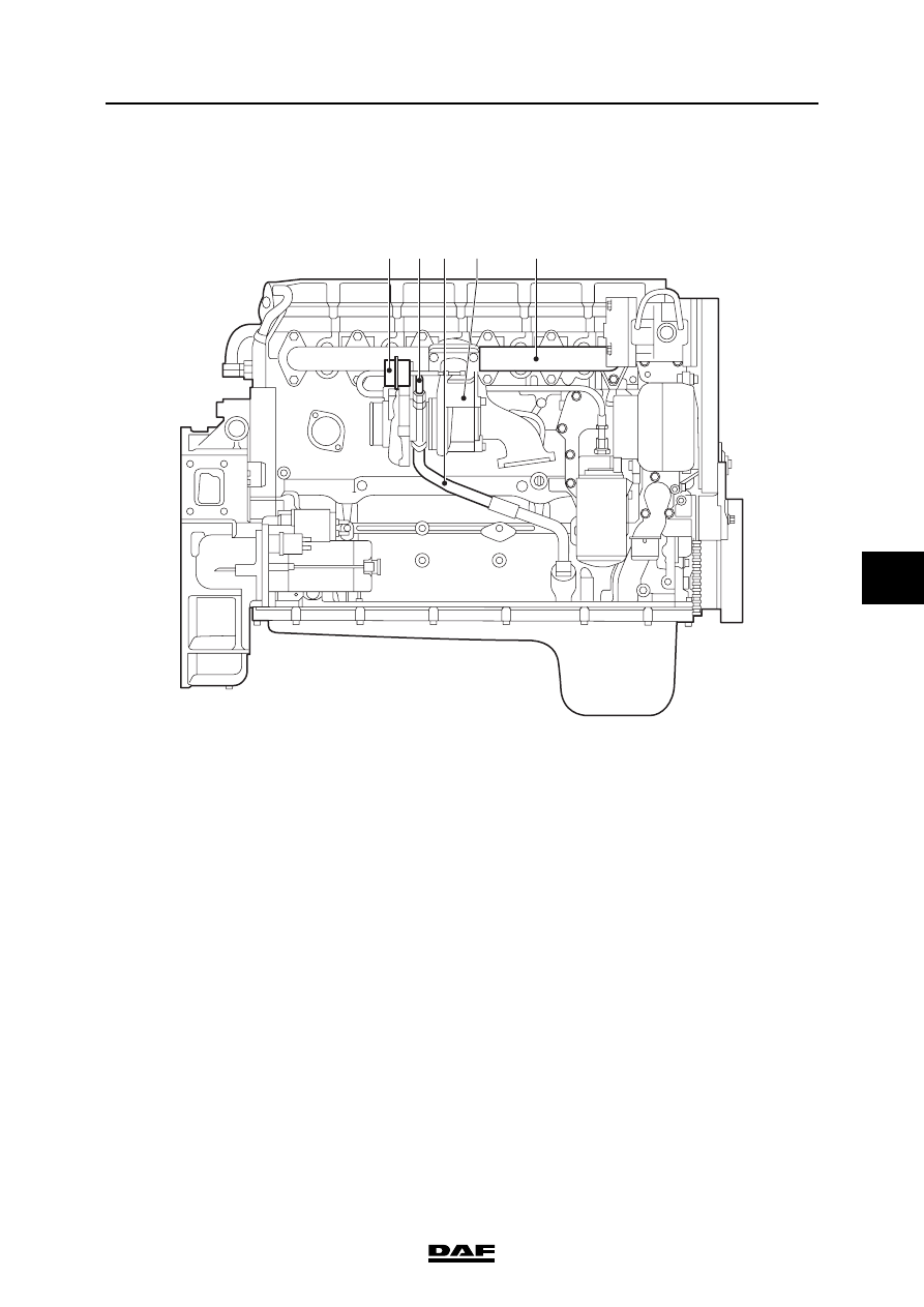
2.1 LOCATION OF COMPONENTS
1.
Wastegate diaphragm box
2.
Oil supply pipe
3.
Oil discharge pipe
4.
Turbocharger
5.
Exhaust manifold
3
4
5
1
2
i400840

CE ENGINE INLET/EXHAUST SYSTEM
2-2
©
200416
General
6
ΛΦ45/55 series
4
1.
Glow element connections
2.
Intake manifold
1
2
i400841
©
200416
2-3
General
CE ENGINE INLET/EXHAUST SYSTEM
ΛΦ45/55 series
4
6
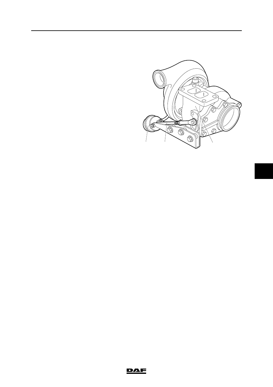
2.2 SYSTEM DESCRIPTION, TURBOCHARGER WITH WASTEGATE
To make the engine more responsive at lower
engine speeds, a turbocharger is used that
produces a better charge ratio at these speeds.
Without provision having been made for this, the
boost pressure yielded by this turbocharger
would be too high at maximum engine speeds.
Use of a wastegate prevents this.
The boost pressure is measured by a diaphragm
box (1) on the delivery side of the turbocharger.
The diaphragm is pushed back against the spring
pressure by the boost pressure. The linked
control rod (2) is also pushed back. The control
rod operates a valve in the turbine housing (3).
The valve in the turbine housing is opened when
the maximum pre-set pressure has been
reached.
When the valve is opened, some of the exhaust
gases will be discharged directly to the exhaust
pipe rather than being used to propel the turbine
rotor of the turbocharger.
i400509
3
2
1
CE ENGINE INLET/EXHAUST SYSTEM
2-4
©
200416
General
6
ΛΦ45/55 series
4
Нет комментариевНе стесняйтесь поделиться с нами вашим ценным мнением.
Текст