DAF LF45, LF55 Series. Manual — part 343
5
LF45/55 series
Removal and installation
WIRING REPAIR
2-3
The contacts may also be locked secondarily by
the lower part of the connector. After tilting this
lower part, the contacts can be removed by
unlocking the primary lock using the proper
ejector tool.
This type of lock is used only on 2-row
connectors.
For example:
-
MTCO connector
E501497
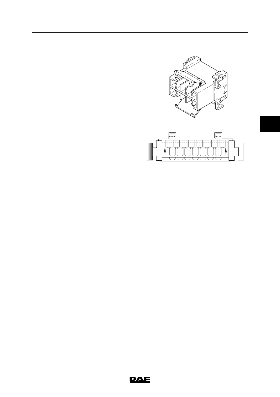
A different type of secondary lock consists of
two sliding parts of the connector.
The upper half (on the wire insert side) and the
lower half form the extra contact lock.
To unlock this secondary contact lock the upper
half of the connector must be pushed away
slightly in the direction of the arrows on the
connector housing.
The contacts can then be removed from the
connector using the proper ejector tool.
After any installation of wires with contacts, the
connector must be pressed into the lock again. If
this is not done it will not fit into the counterpart.
Application examples:
-
connector for CDS electronic unit
-
connector for ECAS-2/3 electronic unit
-
connector for UPEC electronic unit
E500475
15
8
14
7
13
6
12
5
11
4
10
3
9
2
1
15
8
14
7
13
6
12
5
11
4
10
3
9
2
1
3
200440
5
WIRING REPAIR
Removal and installation
LF45/55 series
2-4
Ejecting contacts
For repair or extension of the wiring a contact
may have to be replaced or added. Using
special ejector tools a contact can be removed
from the connector without being damaged.
For the proper ejector tools, see “Parts Rapido”.
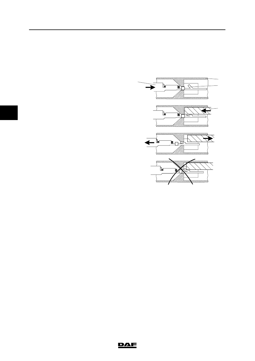
1. Push the wire with contact forwards (1). The
locking bolt (2) is now free from the
connector (3).
2. Push the proper ejector tool (4) into the
front of the connector. This will push the
locking bolt (2) down.
3. The contact can now be removed by gently
pulling the wire.
Note:
If the wire is pulled before the ejector tool
pushes the locking bolt down, the contact will
only be fixed in the connector even more.
E501482
1
2
4
3
3
200440

5
LF45/55 series
Removal and installation
WIRING REPAIR
2-5
Contacts are also used in which the locking
bolt (2) is on the rear of the connector (3).
1. Pull the wire and contact backwards (1).
The locking bolt (2) is now free from the
connector (3).
2. Push the proper ejector tool (4) into the
back of the connector. This will push the
locking bolt (2) up.
3. The contact can now be removed by gently
pushing the wire forwards.
Note:
Here the locking bolt works exactly the opposite
to the usual connectors.
Application examples:
-
EMAS pressure sensor connector
-
accelerator sensor connector for CF series /
XF series
For each contact a specific ejector tool is
required.
The proper ejector tool for each contact can be
found through “Parts Rapido”.
E501696
1
4
2
3
Locking an MQS (Micro Quadlock
System) contact
Before the contact can be removed, the lock
must be unlocked with a needle-shaped object.
1. First press the lock at the end of the
connector (1). At the same time gently pull
the wire (2) until resistance is felt.
2. Then press the second lock (3) and again
gently pull the wire (2).
3. The contact can now be removed from the
connector.
Note:
This type of contact is locked twice and must
therefore be unlocked twice.
Application example:
-
connector for VIC electronic unit
E501486
1
3
2
3
200440

5
WIRING REPAIR
Removal and installation
LF45/55 series
2-6
Removing contacts from the Bosch 89-pin
connector
To remove a contact from this connector
proceed as follows:
1. Fold the protective cover around the wiring
harness down by pushing the lock
outwards.
2. Now push the two outer halves of the
protective cover outwards and then
upwards. The protective cover can now be
removed.
3. The pink secondary contact lock (1) must
be slid to the centre of the connector to
enable the contacts to be removed.
4. The contacts can now be removed using
the proper ejection tool.
Note:
The larger contacts are locked with four locking
bolts. The smaller contacts are locked with two
locking bolts.
Always unlock the locks when adding contacts!
E501485
1
Fitting the Bosch 89-pin connector
When refitting the protective cover, ensure that
the siphon and slide are both in the “unlocked”
position.
If they are not, the connector, when fitted, will
not be locked correctly on the electronic unit. As
a result, the contact between the connector and
the electronic unit may be bad.
Application example:
-
connector for ECS-DC3 electronic unit
E501498
3
200440
Нет комментариевНе стесняйтесь поделиться с нами вашим ценным мнением.
Текст