DAF LF45, LF55 Series. Manual — part 341
5
LF45/55 series
Contents
WIRING REPAIR
1
CONTENTS
Page
Date
1. GENERAL
1-1
200440
. . . . . . . . . . . . . . . . . . . . . . . . . . . . . . . . . . . . . . . . . . . . . . . . . . . . . . . . . . . .
. . . .
1.1
Connector
1-1
200440
. . . . . . . . . . . . . . . . . . . . . . . . . . . . . . . . . . . . . . . . . . . . . . . . . . . . . . .
. . . .
1.2
Contact
1-1
200440
. . . . . . . . . . . . . . . . . . . . . . . . . . . . . . . . . . . . . . . . . . . . . . . . . . . . . . . . . .
. . . .
1.3
Contact kits
1-2
200440
. . . . . . . . . . . . . . . . . . . . . . . . . . . . . . . . . . . . . . . . . . . . . . . . . . . . . .
. . . .
2. REMOVAL AND INSTALLATION
2-1
200440
. . . . . . . . . . . . . . . . . . . . . . . . . . . . . . . . . . . . . . . . .
. . . .
2.1
Removal and installation, connectors
2-1
200440
. . . . . . . . . . . . . . . . . . . . . . . . . . . . . . . .
. . . .
2.2
Removal and installation, contacts
2-2
200440
. . . . . . . . . . . . . . . . . . . . . . . . . . . . . . . . . .
. . . .
2.3
Fitting contacts to electrical wires
2-9
200440
. . . . . . . . . . . . . . . . . . . . . . . . . . . . . . . . . . .
. . . .
2.4
Fitting a SCAT seal
2-16
200440
. . . . . . . . . . . . . . . . . . . . . . . . . . . . . . . . . . . . . . . . . . . . . . . .
. . .
2.5
Fitting an electrical buffer connection
2-17
200440
. . . . . . . . . . . . . . . . . . . . . . . . . . . . . . . .
. . .
2.6
Removal and installation, earth wire
2-19
200440
. . . . . . . . . . . . . . . . . . . . . . . . . . . . . . . . .
. . .
2.7
Repairing CAN network wiring
2-20
200440
. . . . . . . . . . . . . . . . . . . . . . . . . . . . . . . . . . . . . .
. . .
3
200440
5
WIRING REPAIR
Contents
LF45/55 series
2
3
200440
5
LF45/55 series
General
WIRING REPAIR
1-1
1. GENERAL
The increasing application of electronics in
vehicles means a much broader range of
connectors, contacts and wiring is being used.
Be sure to pay special attention to this during
repairs, so as to avoid unnecessary faults.
1.1 CONNECTOR
A connector is a removable connection between
two or more electrical wires or components. The
female contacts are on one side and the male
contacts on the other side. This way they can be
connected and disconnected.
The connector should protect the contacts
against unwanted electrical connections and
external influences. It also ensures the proper
connection of the applicable contacts.
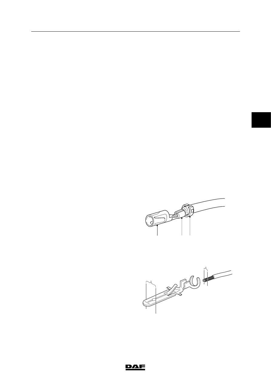
1.2 CONTACT
A connector has one or more contacts. These
contacts are available in various sizes and
models.
However, they all have the same design:
The mating part (1) enables the electrical
connection between the contacts.
The contact press part (2) is the electrical
connection between the stripped part of the wire
and the contact.
The relief part (or pull relief) (3) relieves the
contact press part from mechanical wear. The
insulation relief is placed over the insulating
sheath and/or the SCAT.
E501479
1
3
2
With contacts, three dimensions are important:
the diameter (1) of the wire to be connected, the
size of the contact press part (2), which is linked
to the wire diameter, and the size of the mating
part (3).
E501504
2
1
3
200440

5
WIRING REPAIR
General
LF45/55 series
1-2
1.3 CONTACT KITS
Contact kit A
Contact kit A (DAF no. 0694960) is available for
the contacts, except SCAT contacts and
micro-timer contacts.
There is a sticker on the inside of the box to
facilitate selection of the contact, contact
crimping tool and ejector tool.
At the top the DAF no. of the contact is shown.
Roman numerals I and II, shown below the
illustrations, refer to the contact crimping tool to
be used.
The numeral or letter added to Roman numeral I
or II indicates the hole in the contact crimping
tool in which the contact is to be placed.
Roman numerals III to VII refer to the type of
ejector tool to be used for removing the contact
from the connector.
The information at the bottom refers to the core
section suitable for the contact.
W 5 03 018
3
200440
Нет комментариевНе стесняйтесь поделиться с нами вашим ценным мнением.
Текст