DAF LF45, LF55 Series. Manual — part 462
©
200436
2-27
Inspection and adjustment
BRAKE SYSTEM AND COMPONENTS
ΛΦ45/55 series
6
4
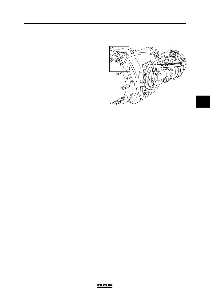
2.19 BRAKE ADJUSTMENT, DISC BRAKE VERSION
1.
Position a feeler gauge between the rear of
the brake pad and one of the thrust pieces of
the brake calliper to check the play.
Compare the measured value (see
"Technical data").
2.
If the play is not correct, it needs to be
adjusted. Remove the covering cap from the
slack adjuster.
3.
Fit a ring spanner on the hexagonal adjusting
bolt and turn the hexagonal adjusting bolt
anticlockwise until there is ample clearance
between the brake pads and the brake disc.
Note:
If Knorr disc brake construction is fitted:
Never turn the hexagonal adjusting bolt
without using an adapter (23). The adapter is
a torque safety and will break off when the
torque is too high. Without the use of an
adapter the mechanics in the brake calliper
may become damaged when the torque is
too high, so that replacement of the brake
calliper may be necessary.
4.
Position a feeler gauge with the correct
thickness (see "Technical data") between
the brake pad and the thrust piece of the
adjuster with the hexagonal adjusting bolt.
5.
Turn the hexagonal adjusting bolt clockwise
with the ring spanner until the feeler gauge
just fits. Remove the feeler gauge.
6.
Apply the brake a number of times so that the
play can set.
7.
Release the brake. Now it should be possible
to turn the hub by hand.
8.
Position a feeler gauge between the rear of
the brake pad and one of the presure plates
of the brake calliper to check the play.
Compare the measured value (see
"Technical data").
9.
After the inspection, lightly grease the
sealing cap (see "Technical data") and
replace it on the slack adjuster.
23
37
1
R600463
BRAKE SYSTEM AND COMPONENTS
2-28
©
200436
Inspection and adjustment
4
ΛΦ45/55 series
6
2.20 INSPECTION, AIR TIGHTNESS
Air tightness
If the brake system of a vehicle has been charged
to the maximum pressure, it should generally be
possible to drive the vehicle away after a period
of 16 hours of uninterrupted standstill, without
first having to charge the brake system to
sufficient operating pressure.
This implies a maximum pressure drop of approx.
0.4 bar per hour at normal system pressure.
Note:
Always connect auxiliary consumers and
accessories to circuit 4.
©
200436
3-1
Removal and installation
BRAKE SYSTEM AND COMPONENTS
ΛΦ45/55 series
6
4
3. REMOVAL AND INSTALLATION
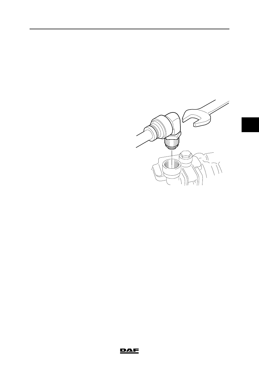
3.1 REMOVAL AND INSTALLATION, QUICK-RELEASE COUPLING
When disconnecting pipes and/or
quick-release couplings, ensure that
the relevant connection has first
been made pressureless.
Removing the quick-release coupling
1.
Loosen the quick-release coupling using an
open-ended spanner.
2.
Remove the quick-release coupling from the
valve.
Installing the quick-release coupling
1.
Check the bore in the valve for dirt and clean
the bore as necessary.
2.
Fit the quick-release coupling to the valve.
3.
Tighten the quick-release coupling to the
specified torque. See "Technical data".
}
R600576
BRAKE SYSTEM AND COMPONENTS
3-2
©
200436
Removal and installation
4
ΛΦ45/55 series
6
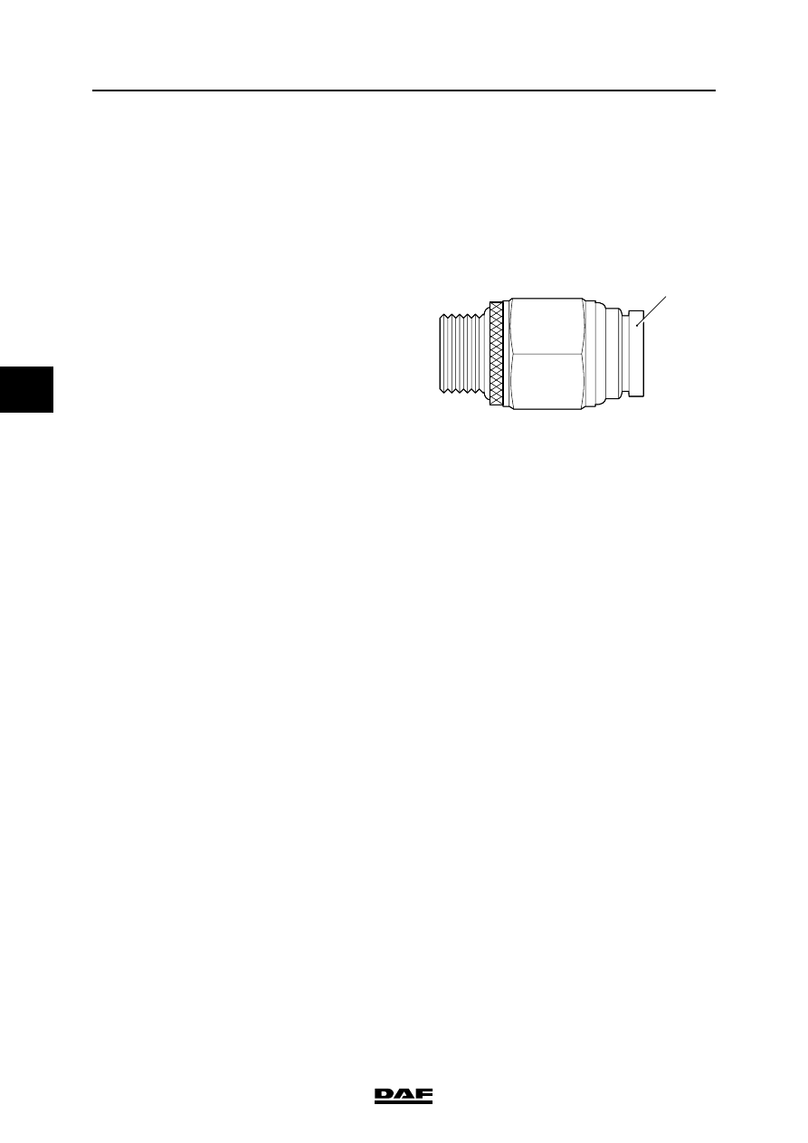
3.2 REMOVAL AND INSTALLATION, PIPE ON QUICK-RELEASE COUPLING
When disconnecting pipes and/or
quick-release couplings, ensure that
the relevant connection has first
been made pressureless.
Removing the pipe on quick-release coupling
1.
Press the collar (1) against the quick-release
coupling.
2.
Press the pipe out of the quick-release
coupling.
Installing the pipe on quick-release coupling
1.
Check the quick-release coupling for
damage. If the quick-release coupling is
damaged, it must be replaced.
2.
Press the pipe into the quick-release
coupling.
3.
Pull out the collar (1).
}
R600575
1
Нет комментариевНе стесняйтесь поделиться с нами вашим ценным мнением.
Текст