DAF LF45, LF55 Series. Manual — part 164
©
200505
3-3
Checking and adjusting
BE ENGINE
ΛΦ45/55 series
2
2
3.2 CHECKING AND ADJUSTING TIMING GEAR
Note:
The engine is fitted with gears on either side. The
gears at the vibration damper end only drive the
oil pump. These gears have no marks and may
be fitted in any position.
The timing gear wheels on the flywheel side drive
the camshaft, air compressor and fuel pump.
Only the camshaft gear and the crankshaft gear
have marks which must be aligned. The other
gears may be fitted randomly.
1.
Remove the engine encapsulation panels.
2.
Remove the gearbox.
3.
Remove the flywheel. See "Removing and
installing".
4.
Remove the flywheel housing. See
"Removing and installing".
Note:
When the engine crankshaft or camshaft is
turned separately, the pistons and valves
may touch each other.
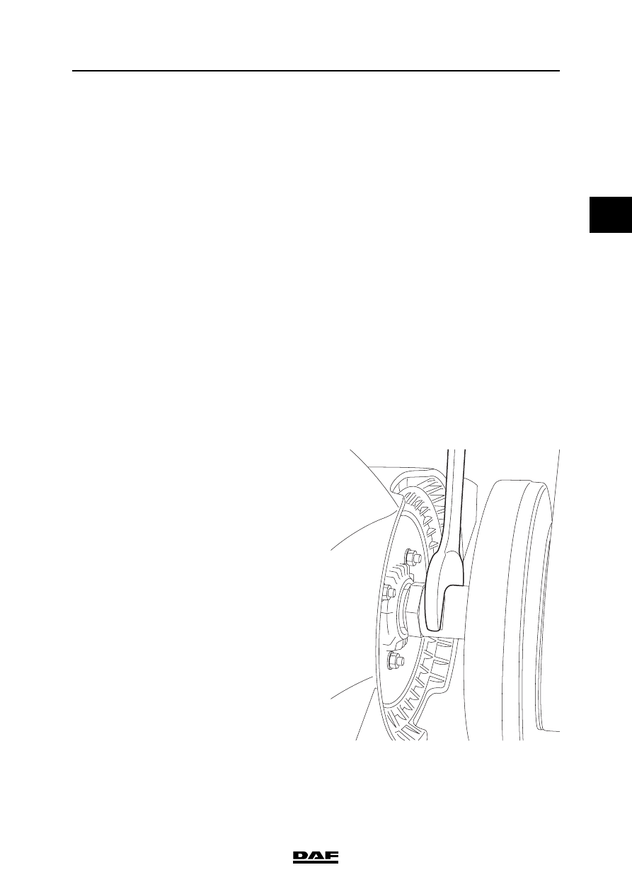
5.
Use an open-end spanner on the fan shaft to
turn the crankshaft clockwise, as seen from
the vibration damper end, until the marks in
the crankshaft gear and camshaft gear
match. The crankshaft gear has a punched
hole in the tooth which has to fall into the
tooth depth of the camshaft gear marked
with a punched hole.
M201318

BE ENGINE
3-4
©
200505
Checking and adjusting
2
ΛΦ45/55 series
2
6.
Check that the marked tooth falls exactly into
the marked depth. If not, remove and refit the
camshaft gear. See "Removing and
installing".
7.
Fit the flywheel housing. See "Removing and
installing".
8.
Fit the flywheel. See "Removing and
installing".
9.
Fit the gearbox.
10. Fit the engine encapsulation panels.
M201146
©
200505
3-5
Checking and adjusting
BE ENGINE
ΛΦ45/55 series
2
2
3.3 CHECKING PISTON PROJECTION
Note:
The piston projection determines which thickness
of cylinder head gasket must be used.
1.
Use an open-end spanner on the fan shaft to
turn the crankshaft, so that the piston of
cylinder 1 is in the top dead centre (TDC).
2.
Clean the upper surface of the cylinder block
and the pistons.
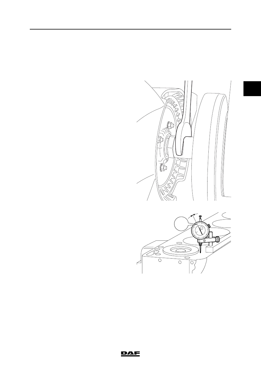
3.
Place a dial gauge on the upper surface of
the cylinder block next to cylinder 1 and set
the gauge to zero.
M201318
M201233
"0"

BE ENGINE
3-6
©
200505
Checking and adjusting
2
ΛΦ45/55 series
2
4.
Pull up the stylus of the dial gauge and move
it to the edge of the first piston, above the
gudgeon pin.
5.
Use an open-end spanner on the fan shaft to
turn the crankshaft anti-clockwise and
clockwise, at the same time reading the dial
gauge to find the highest position of the
piston. Make a note of this reading.
6.
Repeat this measurement for the other
pistons.
7.
Calculate the average value of the piston
projection above the cylinders.
M201234
Нет комментариевНе стесняйтесь поделиться с нами вашим ценным мнением.
Текст