DAF LF45, LF55 Series. Manual — part 163
©
200505
2-3
General
BE ENGINE
ΛΦ45/55 series
2
2
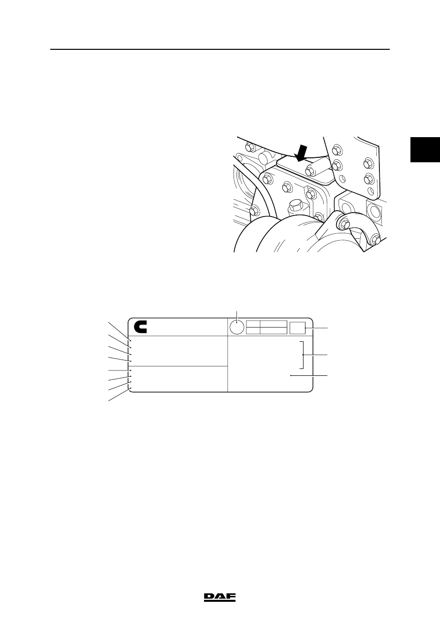
2.2 IDENTIFICATION
Engine number
The engine number is stamped front right in the
cylinder block, at the top of the lubricating oil
cooler housing.
Engine identification plate
The engine identification plate is located at the
top of the flywheel housing or on the valve cover,
depending on the production date.
1.
Cubic capacity
2.
Engine output
3.
Valve clearance
4.
Idle engine speed
5.
Engine number
6.
Production date
7.
Client specification
8.
DAF type designation
9.
Indication of country of origin
10. Free acceleration smoke level (K factor)
11. Type approval numbers
12. Cummins type designation
XXXXXXX
M2 01 138
MADE IN GREAT BRITAIN BY
CUMMINS ENGINE CO LTD
www.cummins.com
Displacement. . . . . . . . . . 5.9 Litres
Gross Power. . . . . . .136kW @ 2500 rpm
Valve lash - (cold)
Int .254 mm, Exh .508 mm
Low idle speed. . . . . . . .. 600 - 800 rpm
Engine Serial No . . . . . . . . . 21410538
Date of mfg . . . . . . . . . . ... 26/06/00
Customer Spec . . . . . . . . . ..1396009
DAF ID . . . . . . . . . . . . ...CE136C
E.C. Type Approal Numbers
e11*72/245*95/54*1413*00(ESA)
e11*88/77*1999/96A*1705*00
Model: - ISBe185 30
3286647
M201135
0.94
E11
24
031410
Cummins
¤
9
10
11
12
5
4
3
2
1
6
7
8
BE ENGINE
2-4
©
200505
General
2
ΛΦ45/55 series
2
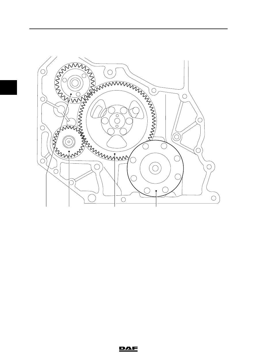
2.3 OVERVIEW DRAWING, TIMING GEAR
1.
Crankshaft
2.
Camshaft
3.
High-pressure pump
4.
Compressor
M201432
1
3
4
2
©
200505
3-1
Checking and adjusting
BE ENGINE
ΛΦ45/55 series
2
2
3. CHECKING AND ADJUSTING
3.1 CHECKING AND ADJUSTING BE ENGINE VALVE CLEARANCE
Note:
Checking and adjusting valve clearance must
only be done when the engine is cold.
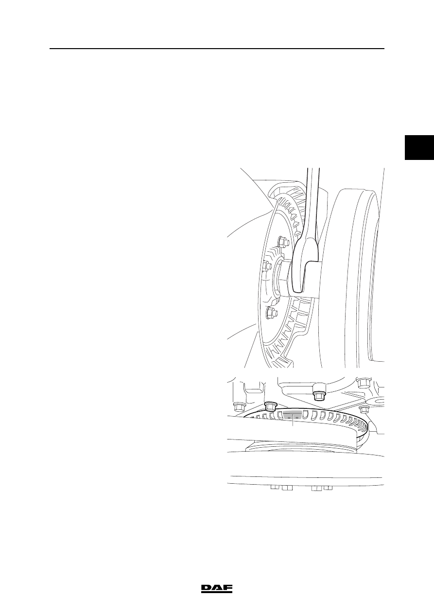
1.
Remove the valve cover. See "Removing
and installing".
2.
Use an open-end spanner on the fan shaft to
turn the crankshaft clockwise, as seen from
the vibration damper end (this is the engine's
normal direction of rotation), until the mark
(A) is between the bolts (B) and the valves of
cylinder 1 are in overlap position.
Note:
"Overlap" is the moment at which the inlet
valves start opening and the exhaust valves
stop closing.
The inlet valves are operated by the short
rockers and the exhaust valves by the long
rockers.
M201318
M201065
A
B
B
BE ENGINE
3-2
©
200505
Checking and adjusting
2
ΛΦ45/55 series
2
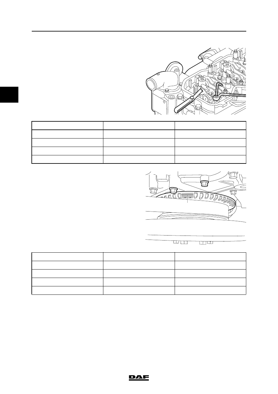
3.
Check/correct the valve clearance of the
specified inlet and exhaust valves. Set the
correct valve clearance by loosening the lock
nut and rotating the adjusting screw in the
correct direction; see "Technical data" for the
correct valve clearance.
4.
Using an open-end spanner on the fan shaft,
turn the crankshaft one rotation further so
that the mark (A) is once again between the
bolts (B) and the valves of cylinder 4 overlap.
5.
Check/correct the valve clearance of the
specified inlet and exhaust valves. Set the
correct valve clearance by loosening the lock
nut and rotating the adjusting screw in the
correct direction; see "Technical data" for the
correct valve clearance.
6.
Fit the valve cover. See "Removing and
installing".
7.
Fit the flexible pipe, air inlet pipe and bracket.
M201064
Cylinder
Inlet valve
Exhaust valve
1
2
X
3
X
4
X
X
M201065
A
B
B
Cylinder
Inlet valve
Exhaust valve
1
X
X
2
X
3
X
4
Нет комментариевНе стесняйтесь поделиться с нами вашим ценным мнением.
Текст