DAF LF45, LF55 Series. Manual — part 383
B
1427090/03
EL001555
54
55
56
57
58
59
60
61
62
63
64
65
66
67
68
69
70
71
72
73
74
75
76
77
78
79
80
81
82
83
84
85
86
87
88
89
90
91
92
93
94
95
96
97
98
99
100
101
102
103
104
105
106
1G
1W
1L
1T
1J
1K
1L
1M
1C
1E
1F
1G
1J
1H
1K
1L
1A
1C
1A
1G
1D
1A
1M
1A
1M
1AV
1YD
1YL
1YM
1AZ
1CU
1G
1F
1H
1P
1Q
1R
1E
1WL
1WE
1CV
1YK
1YG
1YF
1WP
1WM
1XA
1XB
1AW
1AX
1CS
1CS
1
1
1
1
1
1C
1E
1F
1G
G516
D529
2
D900
A5
D900
E5
D851
14
C774
3
C804
1
C871
4
E587
2
B032
1
C748
B
B017
2
C062
2
C763
9
C763
8
C804
B
C727
B
C774
B
C867
B
C725
B
C765
B
D521
7
D926
8
2
754
B1
718
B2
718
1
814
1
781
1
819
1
815
10
738
10
739
C145
1
C144
1
C110
4
C111
4
C159
1
C865
3
C865
8
C868
3
B199
4
C866
10
C866
3
C866
8
C865
10
B200
4
C864
8
C864
3
B018
2
G397
86
C063
2
C864
10
G507
G528
G529
D931
8
D916
8
C715
B
C158
2
C119
2
C736
8
C736
B
C736
1
!
200440
2-21
5
ELECTRICAL SYSTEM
Electrical system
series
45/55
LF

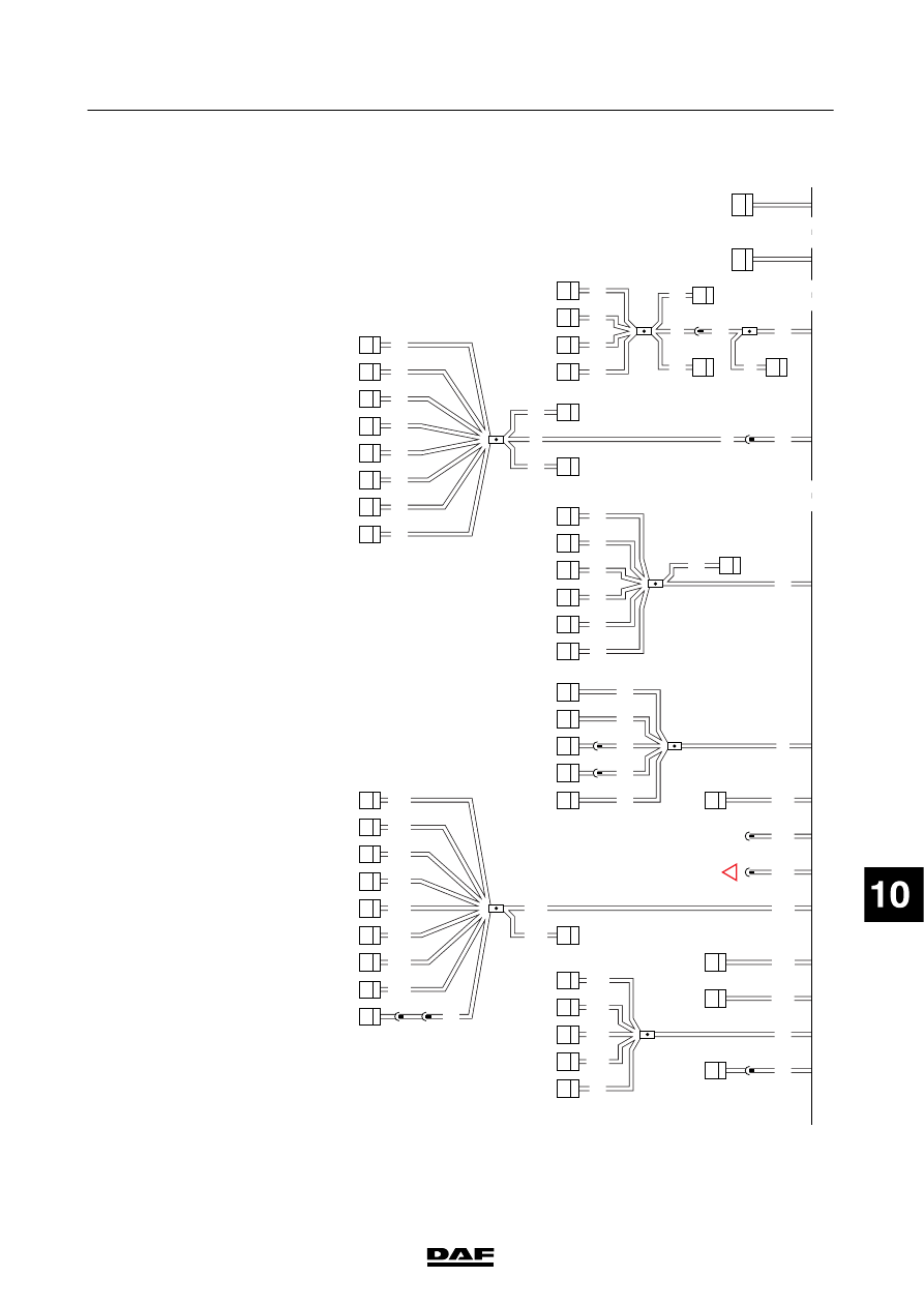
C
CAN
OVER
VIEW
This
section
diagram
gives
an
overview
of
all
the
C
AN
connections,
w
ith
w
ire
m
arkings
and
connector
points.
SEE
THE
SYSTEM
MANUAL
FOR
M
ORE
INFORMA
T
ION
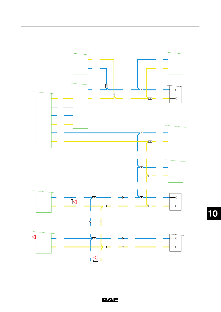
VARIANTS
Location 2
T
he
terminating
resistor
is
in
the
automatic
transmission
wiring
harness
8
E
lectronic
unit,
automatic
gearbox,
AGC-T1000/2000
(D936):
If
MD3060
gearbox
is
fitted,
the
electronic
unit
is
for
AGC-A4
automatic
gearbox
operation
(D866)
16
The
terminating
resistor
is
in
the
wiring
harness
of
the
ECS-DC3
engine
management
system
200440
2-22
5
ELECTRICAL SYSTEM
Electrical system
series
45/55
LF
C
1427090/03
EL001556
1
2
3
4
5
6
7
8
9
10
11
12
13
14
15
16
17
18
19
20
21
22
23
24
25
26
27
28
29
30
31
32
33
34
35
36
37
38
39
40
41
42
43
44
45
46
47
48
49
50
51
52
53
3700D
3700K
3701D
3700C
3701C
3701K
3700E
3700E
3700M
3701E
3700E
3701E
3701E
3700E
3701E
3700E
3700E
3700E
3701E
3701E
3701E
3700E
3701E
3701M
3700G
3701G
3701N
3700N
3701E
3700E
3701E
3700E
3701E
3700E
3701J
3700J
3700B
3700F
3701B
3700L
3701L
3701H
3700H
3701F
3700A
3701A
3566
3565
B20/
797
B21/
797
D911
A1/
820
A3/
820
D961
C15/
745
C14/
745
C2/
745
C1/
745
D18/
746
D20/
746
D900
11/
755
13/
755
D899
3/
775
4/
775
D912
B52/
757
B53/
757
D903
D936
120
Ω
A8/
752
A4/
752
B525
A021
15
16
A032
DC
A087
21
2
724
6
850
1
724
1
850
12/
755
14/
755
7/
755
5/
755
120
Ω
!
!
!
829
7
829
6
B32/
853
B29/
853
200440
2-23
5
ELECTRICAL SYSTEM
Electrical system
series
45/55
LF

1.
MAIN
SWITCH
MANUALL
Y
OPERA
T
ED
EARTH
BREAKER
Tu
rning
m
ain
switch
C
553
anti-clockwise
w
ill
break
the
earth
connection
between
the
batteries
(A500)
and
the
chassis
earth
point
G525.
Because
the
tachograph
(B525)
must
have
a
power
supply
and
earth
connection
at
all
times,
earth
wire
9001
is
connected
directly
to
the
earth
connection
of
the
batteries
through
2-pin
dashboard
lead-through
connector
813
in
zone
1.
200440
2-24
5
ELECTRICAL SYSTEM
Electrical system
series
45/55
LF
Нет комментариевНе стесняйтесь поделиться с нами вашим ценным мнением.
Текст