DAF LF45, LF55 Series. Manual — part 384
1
1427090/03
EL001558
123456789
1
0
1
1
1
2
1
3
1
4
1
5
1
6
1
7
1
8
1
9
2
0
2
1
2
2
2
3
2
4
2
5
2
6
2
7
2
8
2
9
3
0
3
1
3
2
3
3
3
4
3
5
3
6
3
7
3
8
3
9
4
0
4
1
4
2
4
3
4
4
4
5
4
6
4
7
4
8
4
9
5
0
5
1
5
2
5
3
1000
1000
1000
1000
9001
9001
1000
A500
1
813
1/705
2/705
B525
A5/
752
E349
80A
2
1
D942
1000
1000
G525
C553
2
1
200440
2-25
5
ELECTRICAL SYSTEM
Electrical system
series
45/55
LF
ELECTRICALL
Y
OPERA
T
ED
MAIN
SWITCH
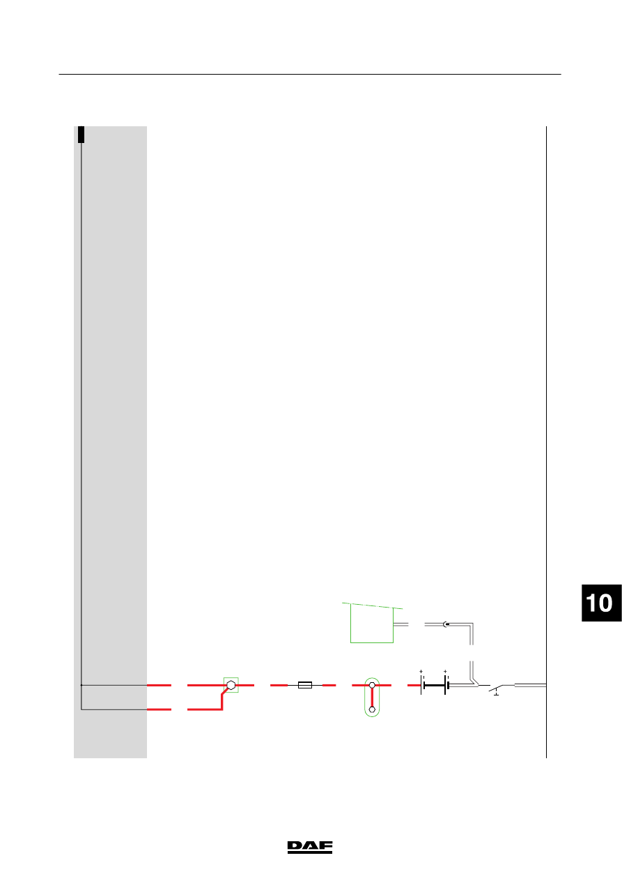
The
m
ain
switch
(D924)
can
be
closed:
-
electrically
in
the
cab
-
elect
rically
on
th
e
chassis
Closing
the
main
switch
electrically
in
the
cab
A
TTENTION:
switch
C854
must
be
in
the
“main
switch
on”
position
(connection
b
etween
contacts
1a
n
d
2)
.
Switch
C853
(switch
for
main
switch
in
cab)
connects
the
C
1
and
C2
connections
to
the
C4
and
C5
connections
via
w
ire
4176,
contacts
5
-
7
of
switch
C
853,
wire
4177,
contacts
1
-
2
of
switch
C
854
and
wire
4178.
Relays
G367
and
G368
are
immediately
energised
through
wire
4174
and
connection
point
A3
(A3
is
connected
to
earth
for
0.5
seconds).
This
closes
the
connection
between
points
88a
and
88
of
both
relay
G367
and
relay
G
368.
The
positive
and
the
negative
terminals
of
the
batteries
are
now
connected
to
the
vehicle’
s
power
supply
.
Immediately
after
switch
C
853
closes,
connection
point
C2
is
internally
connected
to
point
A7.
Connection
point
A5
is
connected
to
the
positive
terminal
via
w
ire
3173
after
connection
point
88
of
relay
G
367.
This
connection
transmits
a
signal
to
the
E
CU
to
indicate
that
relay
G
367
has
switched.
Closing
the
main
switch
electrically
on
the
chassis
A
TTENTION:
switch
C853
must
be
in
the
“main
switch
on”
position
(connection
b
etween
contacts
5a
n
d
7)
.
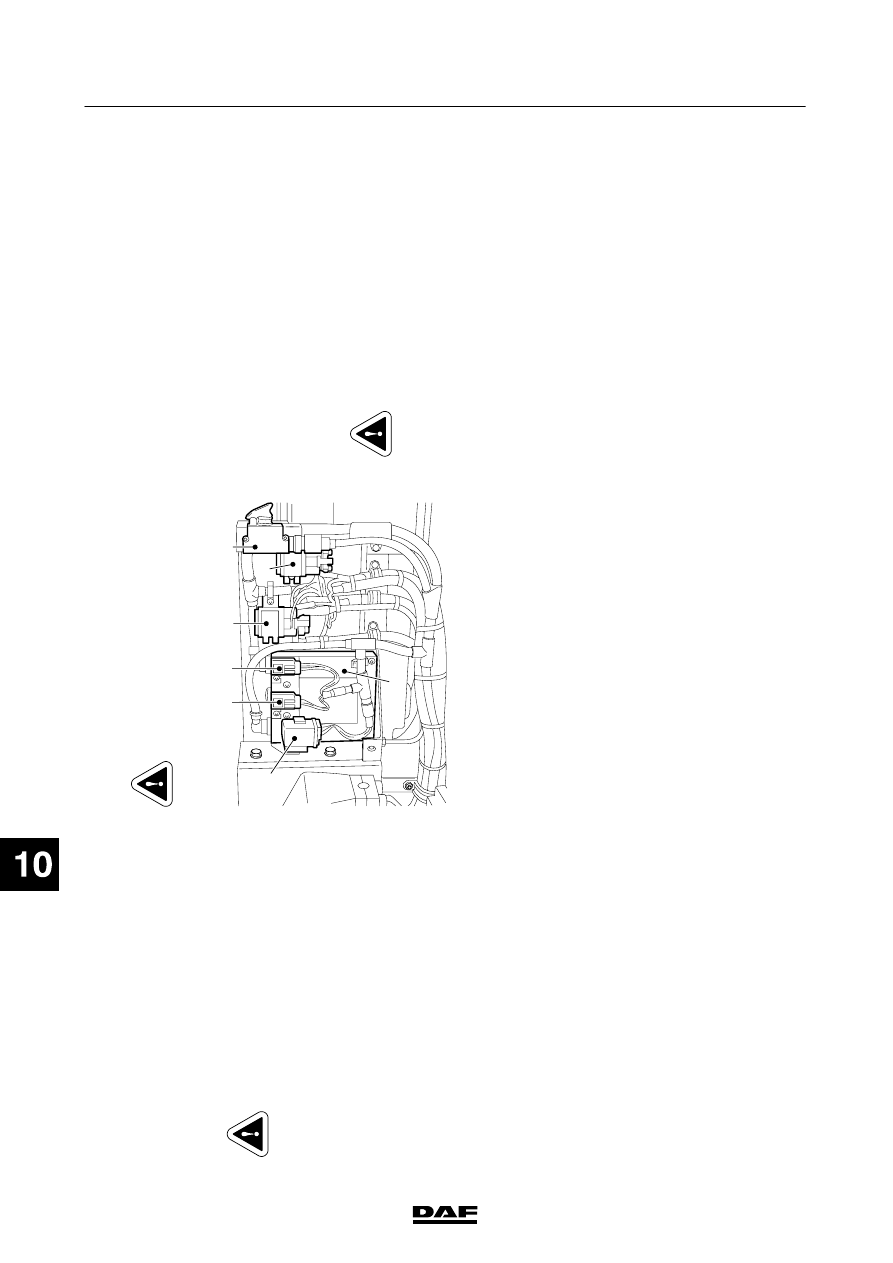
E501695
E153
G425
D924
E330
G367
C854
G368
Switch
C854
(switch
for
main
switch
on
the
chassis)
connects
the
C
1
connection
to
the
C4
and
C5
connections
via
w
ire
4176,
contacts
5
-
7
of
switch
C
853,
wire
4177,
contacts
1
-
2
of
switch
C
854
and
wire
4178.
Relays
G367
and
G368
are
immediately
energised
through
wire
4174
and
connection
point
A3
(A3
is
connected
to
earth
for
0.5
seconds).
This
closes
the
connection
between
points
88a
and
88
of
both
relay
G367
and
relay
G
368.
The
positive
and
the
negative
terminals
of
the
batteries
are
now
connected
to
the
vehicle’
s
power
supply
.
Immediately
after
switch
C
854
closes,
connection
point
C2
is
internally
connected
to
point
A7.
Connection
point
A5
is
connected
to
the
positive
terminal
via
w
ire
3173
after
connection
point
88
of
relay
G
367.
This
connection
transmits
a
signal
to
the
E
CU
to
indicate
that
relay
G
367
has
switched.
The
m
ain
switch
(D924)
can
be
opened:
-
electrically
in
the
cab
-
elect
rically
on
th
e
chassis
Opening
the
main
switch
electrically
in
the
cab
A
TTENTION:
switch
C854
must
be
in
the
“main
switch
on”
position
(connection
b
etween
contacts
1a
n
d
2)
.
Switch
C853
(switch
for
main
switch
in
cab)
disconnects
wire
4176,
contacts
5
-
7
of
switch
C853,
wire
4177,
contacts
1
-
2
of
switch
C854
and
the
C
1
and
C2
connections
from
the
C
4
and
C5
connections
via
w
ire
4178.
200440
2-26
5
ELECTRICAL SYSTEM
Electrical system
series
45/55
LF
Tw
o
actions
are
carried
out
immediately
after
switch
C853
is
opened:
1.
Connection
point
A7
is
connected
to
earth
(A2).
2.
After
a
delay
of
approx.
6
seconds,
relays
G367
and
G368
are
connected
to
earth
for
approx.
0.5
sec.
via
w
ire
4175
and
connection
point
A4.
T
his
breaks
the
connection
between
points
88a
and
88
of
relays
G367
and
G368.
The
positive
and
the
negative
terminals
of
the
batteries
are
now
disconnected
from
the
vehicle’
s
power
supply
.
If
the
engine
is
running,
it
is
switched
of
f.
Connection
point
A5
is
connected
to
the
positive
terminal
via
w
ire
3173
after
connection
point
88
of
relay
G
367.
This
connection
transmits
a
signal
to
the
E
CU
to
indicate
that
relay
G
367
has
switched.
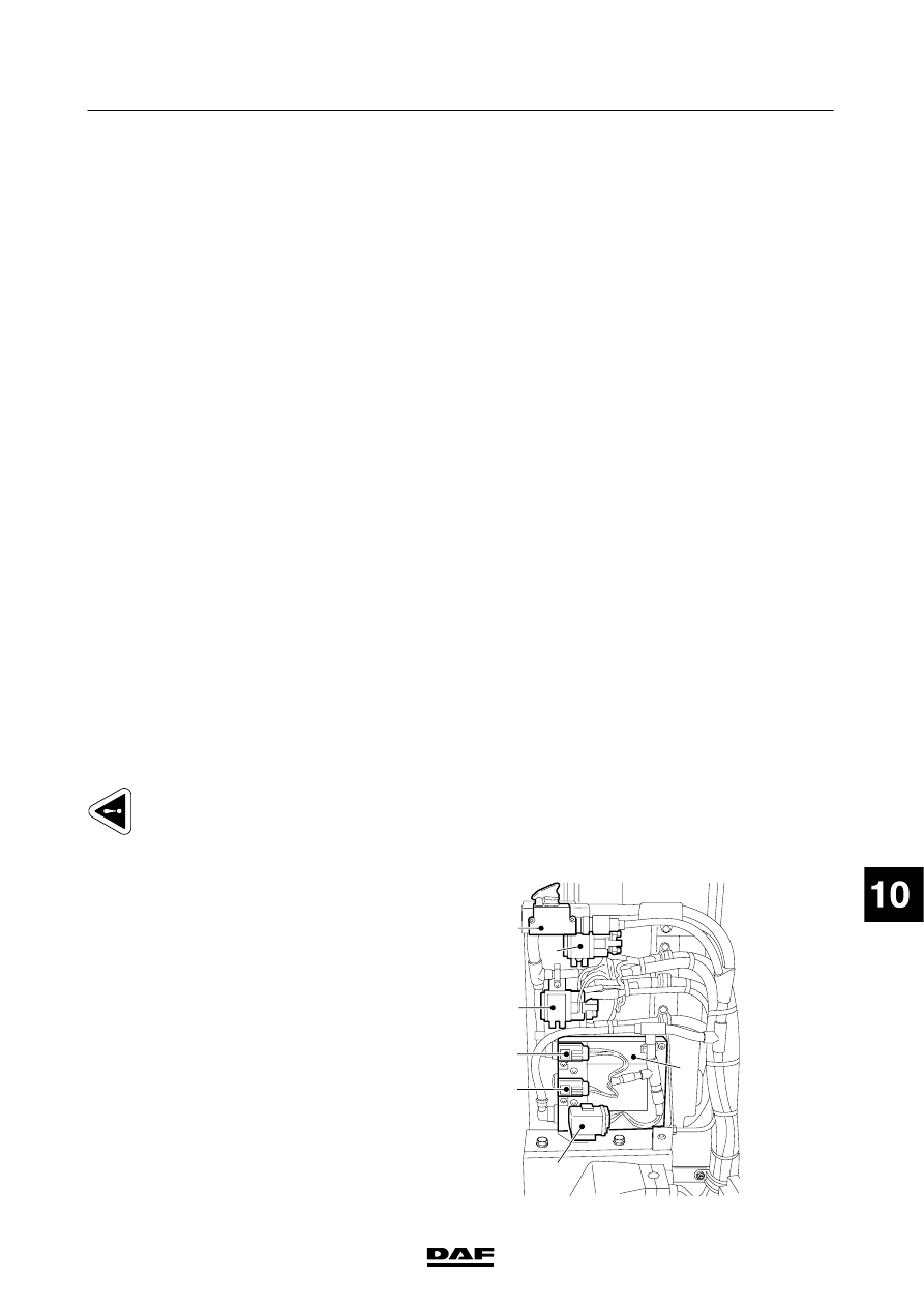
Opening
the
main
switch
electrically
on
the
chassis
E501695
E153
G425
D924
E330
G367
C854
G368
A
TTENTION:
switch
C853
must
be
in
the
“main
switch
on”
position
(connection
b
etween
contacts
5a
n
d
7)
.
Switch
C854
(switch
for
main
switch
in
cab)
breaks
the
C1
and
C2
connections
to
the
C
4
and
C5
connections
via
w
ire
4176,
contacts
5
-
7
of
switch
C
853,
wire
4177,
contacts
1
-
2
of
switch
C854
and
wire
4178.
Tw
o
actions
are
carried
out
immediately
after
switch
C854
is
opened:
1.
Connection
point
A7
is
connected
to
earth
(A2)
in
the
unit.
2.
After
a
delay
of
approx.
6
seconds,
relays
G367
and
G368
are
connected
to
earth
for
approx.
0.5
seconds
via
w
ire
4175
and
connection
point
A4.
T
his
breaks
the
connection
between
points
88a
and
88
of
relays
G367
and
G368.
The
positive
and
the
negative
terminals
of
the
batteries
are
now
disconnected
from
the
vehicle’
s
power
supply
.
If
the
engine
is
running,
it
is
switched
of
f.
Connection
point
A5
is
connected
to
the
positive
terminal
via
w
ire
3173
after
connection
point
88
of
relay
G
367.
This
connection
transmits
a
signal
to
the
E
CU
to
indicate
that
relay
G
367
has
switched.
Note: When
one
of
the
switches
(C853
or
C854)
that
activate
the
electronic
unit
(close
m
ain
switch)
is
operated,
relays
G367
and
G368
are
activated
after
approximately
3
seconds.
If
one
of
the
switches
is
operated
again
w
ithin
the
3
seconds,
the
electronic
unit
(D924)
will
select
the
priority
‘main
switch
ON’.
VARIANTS
Location 76
G368,
main
switch
relay
,earth
fitted
depending
on
the
requirements
for
transporting
hazardous
substances
88,90
These
w
ires
are
only
present
if
ADR
is
fitted
94
Earth
connection
to
connector
834
is
only
present
if
ADR
is
fitted
97
Connector
831:
Only
present
if
th
e
syst
em
is
fit
te
d
w
ith
an
external
current
limiter
(D826)
98,101
Connector
832:
Only
present
if
th
e
syst
em
is
fit
te
d
w
ith
an
external
current
limiter
(D826)
99
Electronic
unit
for
VLG
current
limiter
(D826):
F
itted
depending
on
the
requirements
for
transporting
hazardous
substances.
V
ersion
with
production
date
<
2002-49:
current
limiter
(D826)
used
as
shown
98,101
V
ersion
w
ith
production
date
>
2002-49:
current
limiter
integrated
into
the
M
TCO
(B525)
200440
2-27
5
ELECTRICAL SYSTEM
Electrical system
series
45/55
LF
200440
2-28
5
ELECTRICAL SYSTEM
Electrical system
series
45/55
LF
Нет комментариевНе стесняйтесь поделиться с нами вашим ценным мнением.
Текст