DAF LF45, LF55 Series. Manual — part 234
©
200508
1-1
General
PNEUMATIC GEARBOX CONTROL
ΛΦ45/55 series
3
3
1. GENERAL
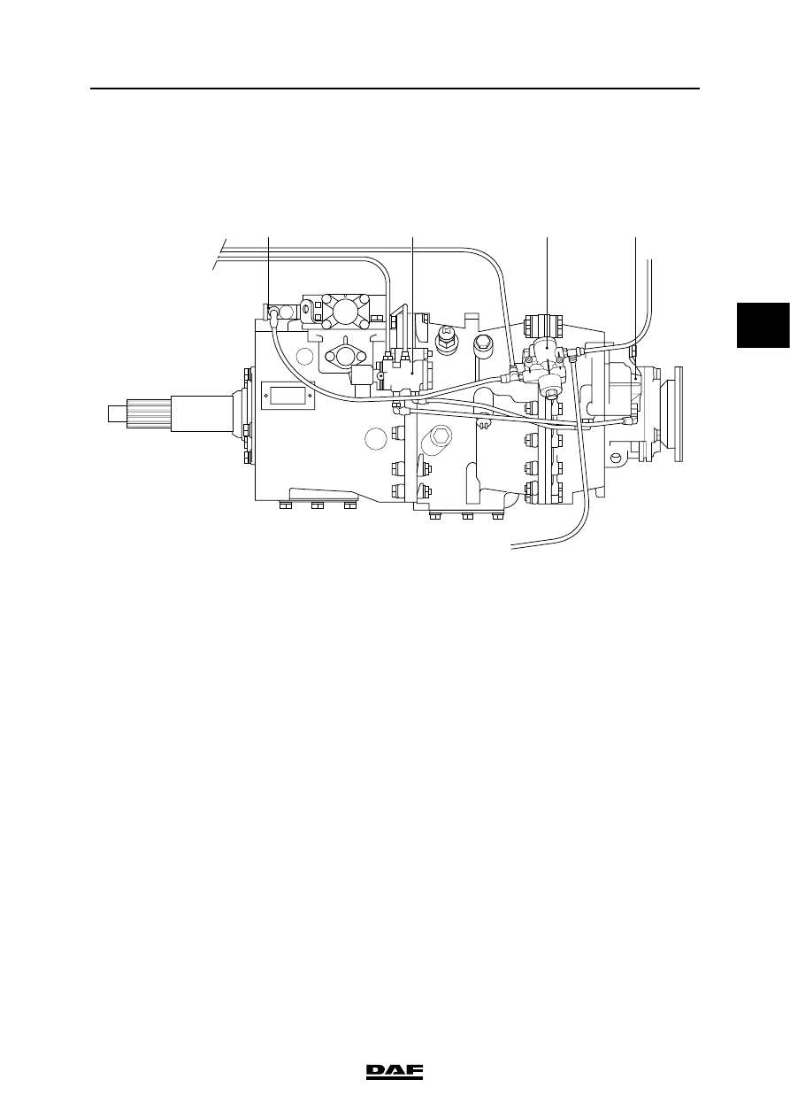
1.1 LOCATION OF COMPONENTS IN PNEUMATIC SECTION OF GEARBOX
CONTROL
1
4
3
2
V3 00 360
1.
Filter/governor
2.
Neutral position valve
3.
Electropneumatic downshift protection valve
4.
Range group engaging cylinder
PNEUMATIC GEARBOX CONTROL
1-2
©
200508
General
3
ΛΦ45/55 series
3
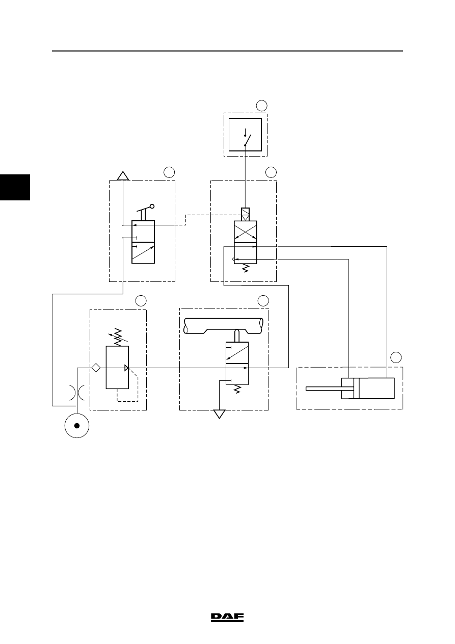
1.2 PNEUMATIC DIAGRAM, GEARBOX CONTROL
N
V
1
1
21
GP
H
L
H
L
4
1
21
22
V3 00 359
4
5
6
2
1
3
+
1.
VIC electronic unit
2.
Electropneumatic downshift protection valve
3.
Range group engaging cylinder
4.
Neutral position valve
5.
Filter/governor
6.
Range group operating switch
L
Position "low"
H
Position "high"
N
Gearbox selector shaft in neutral
V
Gearbox selector shaft engaged
©
200508
1-3
General
PNEUMATIC GEARBOX CONTROL
ΛΦ45/55 series
3
3
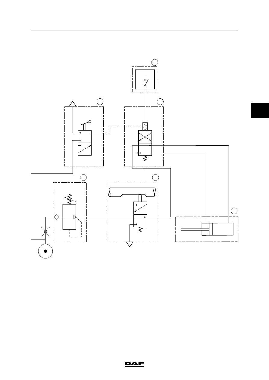
1.3 SYSTEM DESCRIPTION, PNEUMATIC SECTION OF GEARBOX CONTROL
The pressure in the pneumatic section of the
gearbox control is filtered and reduced in the
filter/governor (5). From the filter/governor the
system pressure goes to the neutral position
valve (4) and the range group operating switch
(6) located on the ball of the gear lever.
When the range group operating switch is
activated a pneumatic command will be sent
to the electropneumatic downshift protection
valve (2).
N
V
1
1
21
GP
H
L
H
L
4
1
21
22
V3 00 359
4
5
6
2
1
3
+
PNEUMATIC GEARBOX CONTROL
1-4
©
200508
General
3
ΛΦ45/55 series
3
The electropneumatic downshift protection valve
can only be activated when the vehicle speed is
below a certain value. This is so as to prevent
damage to the drive line. When the vehicle speed
is low enough, the electropneumatic downshift
protection valve is activated and the system
pressure goes from the neutral position valve to
the range group engaging cylinder.
The neutral position valve is activated when the
gear lever is moved through the neutral position.
Нет комментариевНе стесняйтесь поделиться с нами вашим ценным мнением.
Текст