DAF LF45, LF55 Series. Manual — part 232
©
200508
3-3
Removal and installation
MECHANICAL GEARBOX CONTROL
ΛΦ45/55 series
3
2
3.3 REMOVING AND INSTALLING GEAR LEVER UNIT
Removing gear lever unit
1.
Remove the switch button.
2.
Remove the gaiter.
3.
Remove the retainer clip from the telescopic
control rod underneath the cab and remove
the gear lever unit.
4.
Remove the attachment bolts of the gear
lever on the bottom of the cab.
Installing gear lever unit
1.
Slide the gear lever unit and the telescopic
control rod onto the gearbox control and fit
the retainer clip.
2.
Install the gear lever in the cab via the feed-
through.
3.
Fit the gear lever attachment bolts and
tighten them to the specified torque. See
"Technical data".
4.
Fit the gaiter.
5.
Fit the switch button.
6.
Check that the operating mechanism does
not touch any vehicle parts during shifting.
MECHANICAL GEARBOX CONTROL
3-4
©
200508
Removal and installation
2
ΛΦ45/55 series
3
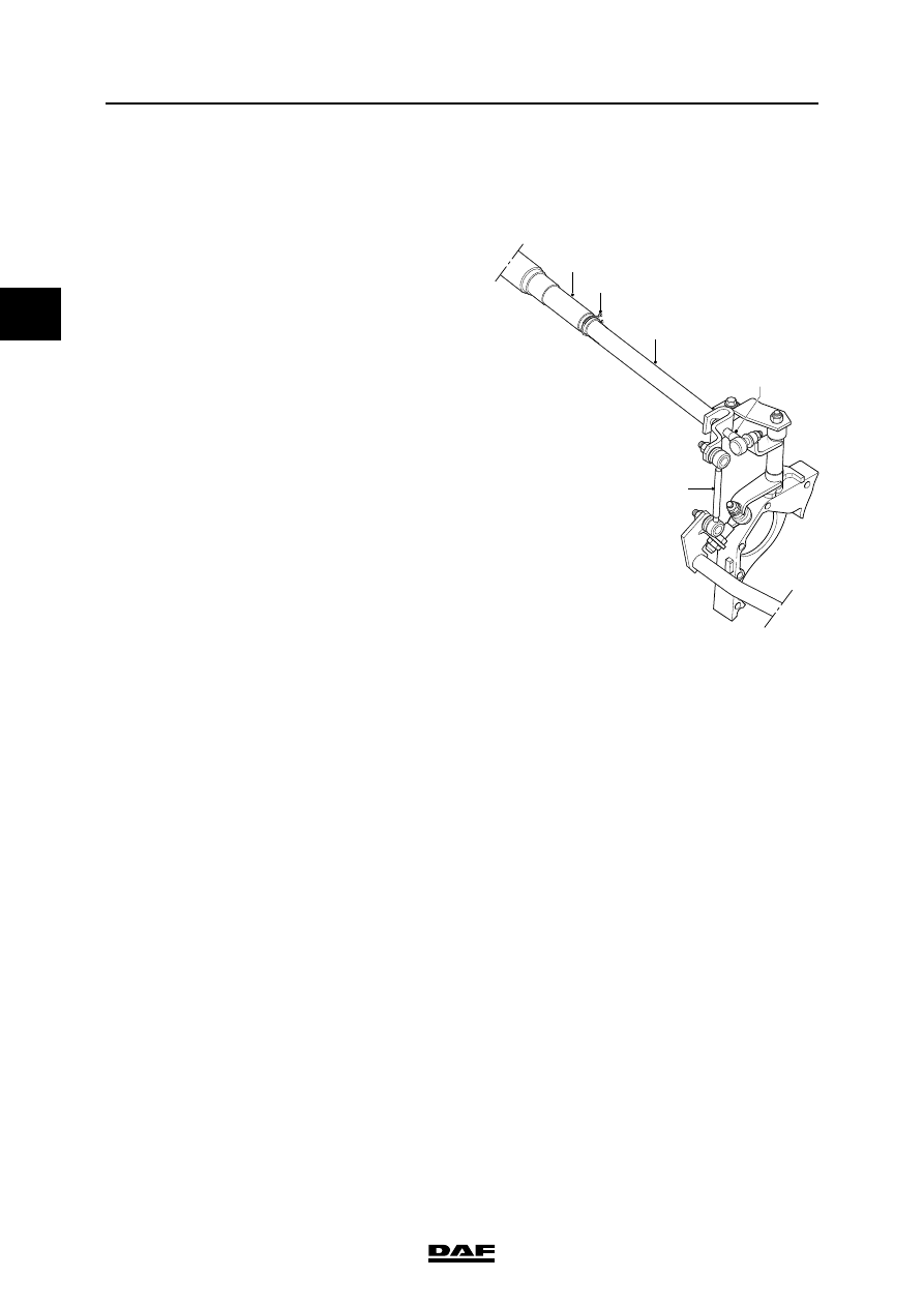
3.4 REMOVING AND INSTALLING CONTROL ROD UNDERNEATH THE CAB
Removing control rod underneath the cab
1.
Remove the retainer clip (2) of the telescopic
control rod (1).
2.
Remove the attachment nuts from the ball
joint (4) and torque rod (5).
1
2
3
4
5
V3 00 573

©
200508
3-5
Removal and installation
MECHANICAL GEARBOX CONTROL
ΛΦ45/55 series
3
2
Installing control rod underneath the cab
1.
Adjust the length (A) of the control rod (3).
See "Technical data".
2.
Clean part (B) of the control rod and remove
any grease.
3.
Apply the specified lubricant lightly to section
(C) of the control rod. See "Technical data".
4.
Fit the control rod (3) into the telescopic
control rod (1) and fit the retainer clip (2).
5.
Tighten the attachment nuts of the ball joint
(4) and the torque rod to the specified torque.
See "Technical data".
6.
Check the functioning of the operating
mechanism. See "Inspection and
adjustment".
V3 00 745
A
C
B
1
2
3
4
5
V3 00 573

MECHANICAL GEARBOX CONTROL
3-6
©
200508
Removal and installation
2
ΛΦ45/55 series
3
3.5 REMOVING AND INSTALLING REAR CONTROL ROD
Removing control rod behind the cab
1.
Remove the attachment nut from the ball
joint (2).
2.
Remove the attachment nut from torque rods
(1) and (4).
3.
Remove the lock nut from the ball joint (5).
Note:
Make sure that the rearmost lock nut on the
ball joint (5) is not moved.
4.
Remove the control rod (3).
V3 00 574
5
1
2
3
4
Нет комментариевНе стесняйтесь поделиться с нами вашим ценным мнением.
Текст