Dodge Dakota (ND). Manual — part 347
WINDOW/DOOR LOCK SWITCH TEST
POWER LOCK SWITCH
SWITCH POSITION
RESISTANCE BETWEEN C-1 PINS 8 & 3
LOCK
330 OHMS ± 5%
UNLOCK
100 OHMS ± 5%
POWER WINDOW SWITCHES - DRIVER DOOR
SWITCH POSITION
CONTINUITY BETWEEN PINS OF C-1
NEUTRAL
PINS 4 (C1) & 6 (C2)
PINS 4 (C1) & 5 (C2)
PINS 4 (C1) & 1 (C2)
PINS 4 (C1) & 4 (C2)
PINS 4 (C1) & 2 (C2)
LEFT FRONT UP
PINS 2 & 7 (C1)
LEFT FRONT DOWN
PINS 2 & 6 (C1)
RIGHT FRONT UP
PINS 2 (C1) & 6 (C2)
RIGHT FRONT DOWN
PINS 2 (C1) & 5 (C2)
LEFT REAR UP
PINS 2 (C1) & 1 (C2)
LEFT REAR DOWN
PINS 2 (C1) & 4 (C2)
RIGHT REAR UP
PINS 2 (C1) & 2 (C2)
RIGHT REAR DOWN
PINS 2 (C1) & 3 (C2)
POWER WINDOW SWITCH - PASSENGER DOOR
UP
PINS 4 & 3
DOWN
PINS 4 & 2
NEUTRAL
PINS 1 & 2 AND 3 & 8
POWER WINDOW LOCKOUT SWITCH
SWITCH POSITION
CONTINUITY BETWEEN
OFF (SWITCH BUTTON RAISED - NOT DEPRESSED)
PINS 2 AND 5 OF C-1
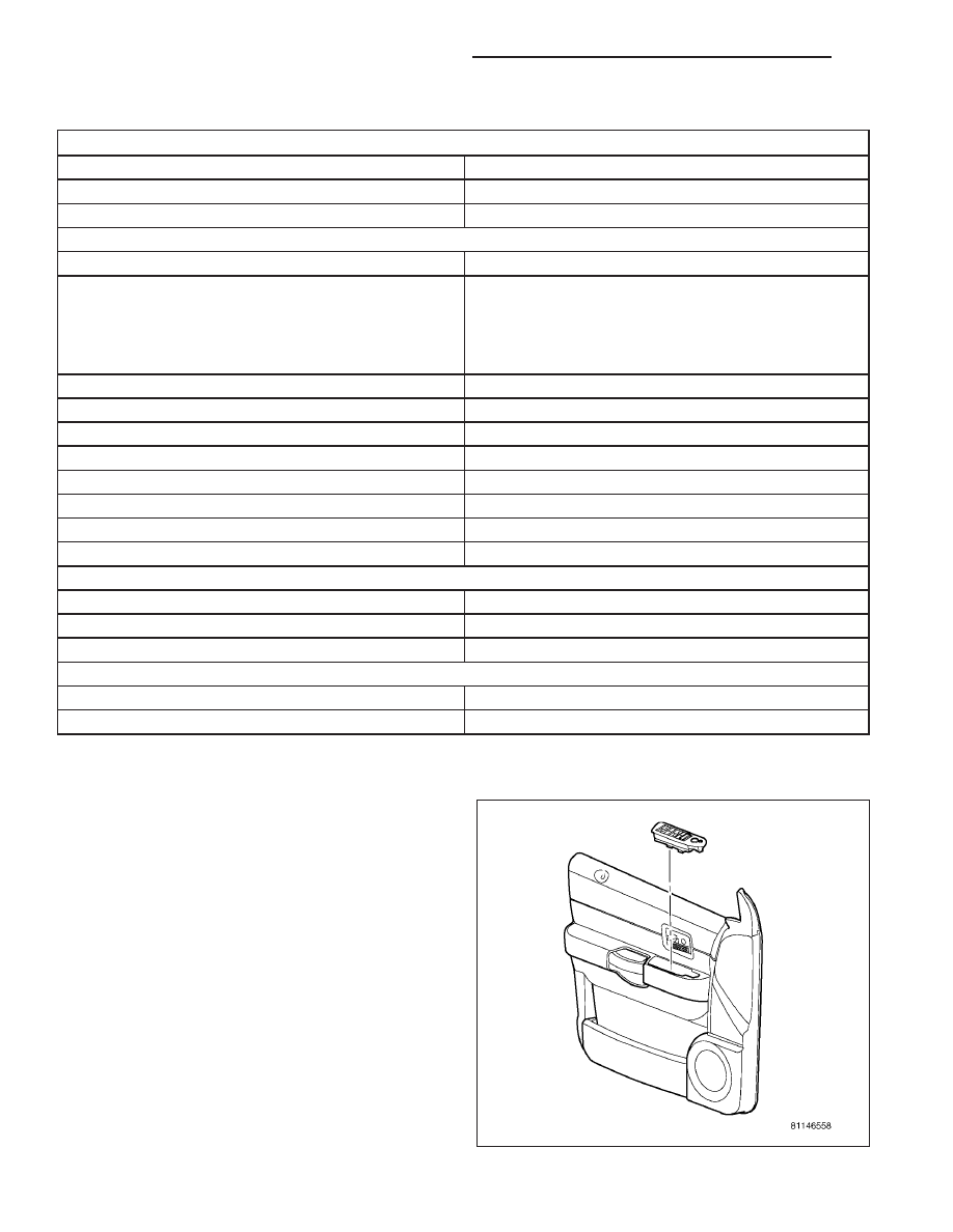
REMOVAL
1. Disconnect and isolate the battery negative cable.
2. Using a trim stick, start at the rear of the switch
and pry up to remove from door trim panel.
3. Disconnect
electrical
harness
connectors
from
switch.
8N - 64
POWER LOCKS - SERVICE INFORMATION
ND
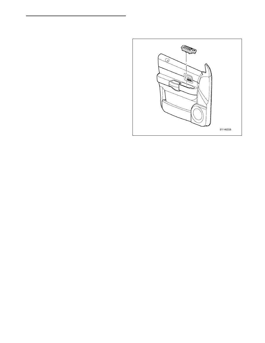
INSTALLATION
1. Connect electrical harness connectors to switch.
2. Insert front end of switch into door trim panel open-
ing. Press into place.
3. Connect battery negative cable.
ND
POWER LOCKS - SERVICE INFORMATION
8N - 65
POWER MIRRORS - SERVICE INFORMATION
TABLE OF CONTENTS
page
page
POWER MIRRORS - SERVICE INFORMATION
. . . . . . . . . . . . . . . . . . . . . . . . . 66
. . . . . . . . . . . . . . . . . . . . . . . . . . . 66
. . . . . . . . . . . . . . . . . . . . 66
MIRROR-INSIDE REARVIEW
. . . . . . . . . . . . . . . . . . . . . . . . . 67
. . . . . . . . . . . . . . . . . . . . . . . . . . . 67
SWITCH-MIRROR
. . . . . . . . . . . . . . . . . . . . . . . . . 68
. . . . . . . . . . . . . . . . . . . . . . . . . . . 68
. . . . . . . . . . . . . . . . . . . . 68
. . . . . . . . . . . . . . . . . . . . . . . . . . . . . 69
. . . . . . . . . . . . . . . . . . . . . . . . . 70
POWER MIRRORS - SERVICE INFORMATION
DESCRIPTION
AUTOMATIC DAY/NIGHT MIRROR
The automatic day/night mirror system is able to automatically change the reflectance of the inside rear view mirror
in order to reduce the glare of headlamps approaching the vehicle from the rear. The automatic day/night rear view
mirror receives battery current through a fuse in the junction block only when the ignition switch is in the On posi-
tion.
OUTSIDE REAR VIEW MIRROR
The power operated rear view mirrors allow the driver to adjust both outside mirrors electrically from the driver side
front seat position by operating a switch on the driver side front door trim panel. The power mirrors receive a non-
switched battery feed through a fuse in the junction block so that the system will remain operational, regardless of
the ignition switch position.
OPERATION
AUTOMATIC DAY/NIGHT MIRROR
A switch located on the bottom of the automatic day/night mirror housing allows the vehicle operator to select
whether the automatic dimming feature is operational. When the automatic day/night mirror is turned on, the mirror
switch is lighted by an integral Light-Emitting Diode (LED). The mirror will automatically disable its self-dimming
feature whenever the vehicle is being driven in reverse.
DIAGNOSIS AND TESTING
POWER MIRRORS
For complete circuit diagrams, refer to the appropriate wiring information.
1. Check the fuses in the Integrated Power Module (IPM). If OK, go to Step 2. If not OK, repair the shorted circuit
or component as required and replace the faulty fuse(s).
2. Check for battery voltage at the fuse in the IPM. If OK, go to Step 3. If not OK, repair the open circuit to the IPM
as required.
3. Disconnect and isolate the battery negative cable. Remove the wire harness connector from the power mirror
switch. Connect the battery negative cable. Check for battery voltage at the fused B(+) circuit cavity in the door
wire harness half of the power mirror switch wire harness connector. If OK, go to Step 4. If not OK, repair the
open circuit to the IPM as required.
8N - 66
POWER MIRRORS - SERVICE INFORMATION
ND
4. Disconnect and isolate the battery negative cable. Check for continuity between the ground circuit cavity in the
door wire harness half of the power mirror switch wire harness connector and a good ground. There should be
continuity. If OK, (Refer to 8 - ELECTRICAL/POWER MIRRORS/POWER MIRROR SWITCH - DIAGNOSIS AND
TESTING) . If not OK, repair open in the ground circuit.
MIRROR-INSIDE REARVIEW
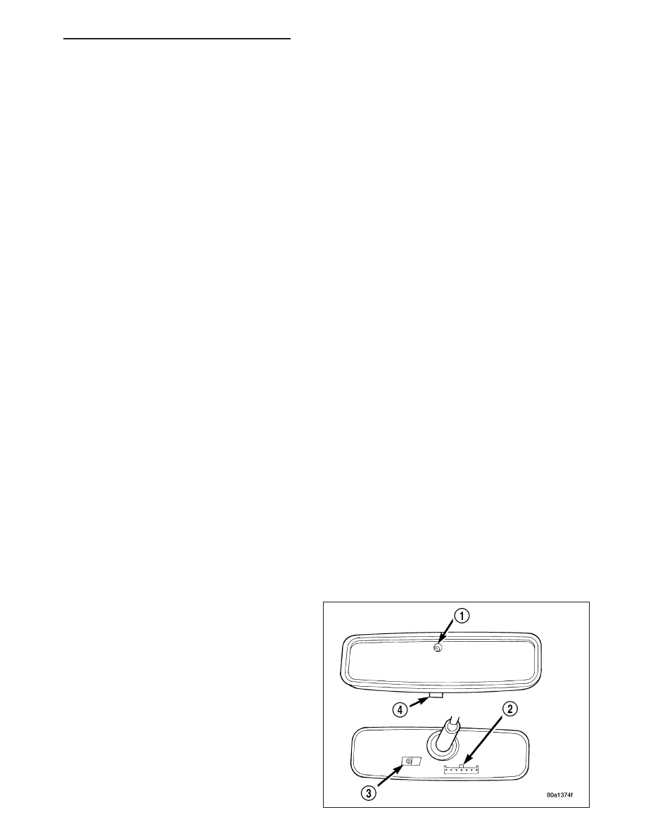
DESCRIPTION
The automatic day/night mirror uses a thin layer of electrochromic material between two pieces of conductive glass
to make up the face of the mirror. When the mirror switch is in the On position, two photocell sensors are used by
the mirror circuitry to monitor external light levels and adjust the reflectance of the mirror.
OPERATION
The ambient photocell sensor is located on the forward-facing (windshield side) of the rear view mirror housing, and
detects the ambient light levels outside of the vehicle. The headlamp photocell sensor is located inside the rear view
mirror housing behind the mirror glass and faces rearward, to detect the level of the light being received at the rear
window side of the mirror. When the circuitry of the automatic day/night mirror detects that the difference between
the two light levels is too great (the light level received at the rear of the mirror is much higher than that at the front
of the mirror), it begins to darken the mirror.
The automatic day/night mirror circuitry also monitors the transmission using an input from the backup lamp circuit.
The mirror circuitry is programmed to automatically disable its self-dimming feature whenever it senses that the
transmission backup lamp circuit is energized.
The automatic day/night mirror is a completely self-contained unit and cannot be repaired. If inoperative or dam-
aged, the entire mirror assembly must be replaced.
DIAGNOSIS AND TESTING
MIRROR - INSIDE REARVIEW
For complete circuit diagrams, refer to the appropriate wiring information.
1. Check the fuse in the Integrated Power Module (IPM). If OK, go to Step 2. If not OK, repair the shorted circuit
or component as required and replace the faulty fuse.
2. Turn the ignition switch to the On position. Check for battery voltage at the fuse in the junction block. If OK, go
to Step 3. If not OK, repair the open circuit to the ignition switch as required.
3. Turn the ignition switch to the Off position. Disconnect and isolate the battery negative cable. Unplug the wire
harness connector from the mirror. Connect the battery negative cable. Turn the ignition switch to the On posi-
tion. Check for battery voltage at the fused ignition switch output (run/start) circuit cavity of the automatic day/
night mirror wire harness connector. If OK, go to Step 4. If not OK, repair the open circuit to the IPM as required.
4. Turn the ignition switch to the Off position. Discon-
nect and isolate the battery negative cable. Check
for continuity between the ground circuit cavity of
the automatic day/night mirror wire harness con-
nector and a good ground. There should be conti-
nuity. If OK, go to Step 5. If not OK, repair the
circuit to ground as required.
5. Connect the battery negative cable. Turn the igni-
tion switch to the On position. Apply the parking
brake. Place the transmission gear selector lever in
the Reverse position. Check for battery voltage at
the backup lamp switch output circuit cavity of the
mirror wire harness connector. If OK, go to Step 6.
If not OK, repair the open circuit as required.
6. Turn the ignition switch to the Off position. Discon-
nect the battery negative cable. Plug in the mirror
ND
POWER MIRRORS - SERVICE INFORMATION
8N - 67
Нет комментариевНе стесняйтесь поделиться с нами вашим ценным мнением.
Текст