Dodge Dakota (ND). Manual — part 345
*RIGHT DOORS LOCK ONLY – QUAD CAB (CONTINUED)
For the Power Door Lock circuit diagram (Refer to 8 - ELECTRICAL/POWER LOCKS - SCHEMATICS AND DIA-
GRAMS).
For a complete wiring diagram Refer to Section 8W.
Possible Causes
(G778) DOOR UNLOCK DRIVER RIGHT DOORS CIRCUIT SHORTED TO GROUND
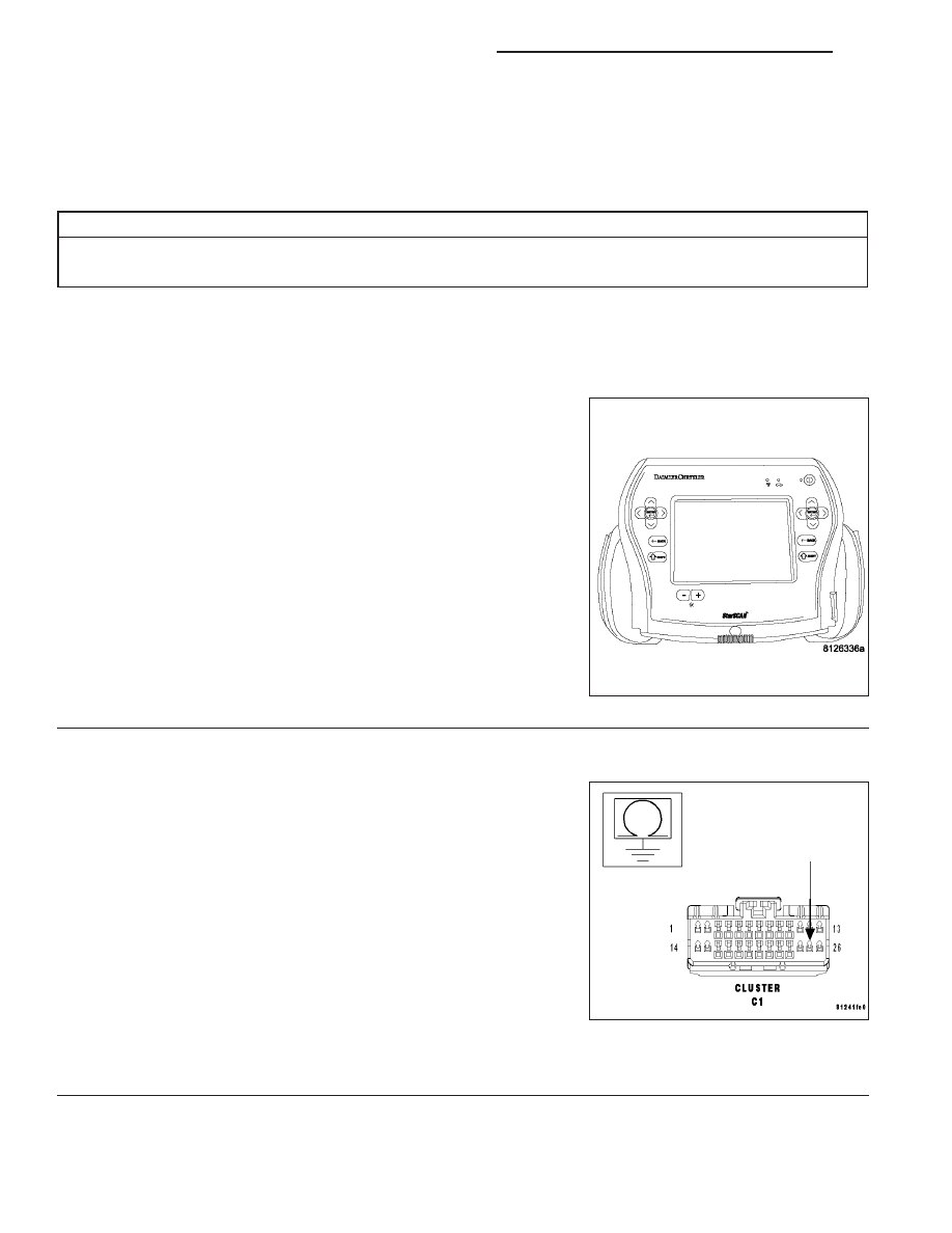
CLUSTER
Diagnostic Test
1.
CHECK FOR ACTIVE DTC’s
Turn the ignition on.
With the scan tool, read active DTC’s.
Does the scan tool display any Door Lock related DTC’s?
No
>> Go To 2
Yes
>> Refer to the symptom list for problems related to Power
Door Locks. Diagnose and repair the DTC’s.
2.
CHECK THE (G778) DOOR UNLOCK DRIVER RIGHT DOORS CIRCUIT FOR A SHORT TO GROUND
Turn the ignition off.
Disconnect the Cluster C1 connector.
Measure the resistance between ground and the (G778) Door Unlock
Driver Right Doors circuit.
Is the resistance below 1000.0 ohms?
No
>> Replace the Cluster in accordance with service informa-
tion.
Perform BODY VERIFICATION TEST - VER 1. (Refer to 8
- ELECTRICAL/POWER LOCKS - DIAGNOSIS AND
TESTING)
Yes
>> Repair the (G778) Door Unlock Driver Right Doors circuit
for a short to ground.
Perform BODY VERIFICATION TEST - VER 1. (Refer to 8 - ELECTRICAL/POWER LOCKS - DIAGNO-
SIS AND TESTING)
8N - 56
POWER LOCKS - ELECTRICAL DIAGNOSTICS
ND
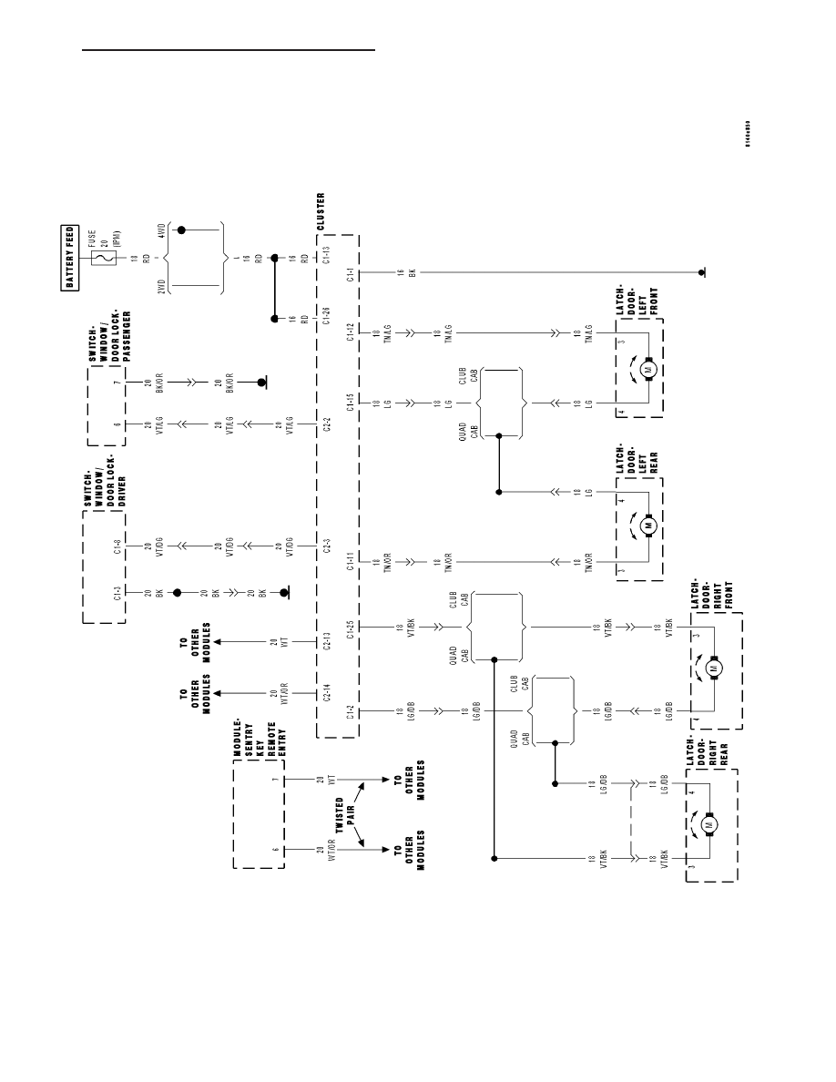
SCHEMATICS AND DIAGRAMS
POWER
DOOR
LOCK
SYSTEM
ND
POWER LOCKS - ELECTRICAL DIAGNOSTICS
8N - 57
POWER LOCKS - SERVICE INFORMATION
TABLE OF CONTENTS
page
page
POWER LOCKS - SERVICE INFORMATION
. . . . . . . . . . . . . . . . . . . . . . . . . 58
. . . . . . . . . . . . . . . . . . . . . . . . . . . 59
. . . . . . . . . . . . . . . . . . . . . . 60
POWER LOCK MOTOR
. . . . . . . . . . . . . . . . . . . . . . . . . 60
. . . . . . . . . . . . . . . . . . . . . . . . . . . 60
. . . . . . . . . . . . . . . . . 61
REMOTE KEYLESS ENTRY TRANSMITTER
REMOTE KEYLESS ENTRY TRANSMITTER
PREFERENCES . . . . . . . . . . . . . . . . . . . . . . . 61
REMOTE KEYLESS ENTRY TRANSMITTER
BATTERIES . . . . . . . . . . . . . . . . . . . . . . . . . . 62
REMOTE KEYLESS ENTRY TRANSMITTER
PROGRAMMING . . . . . . . . . . . . . . . . . . . . . . 62
REMOTE KEYLESS ENTRY TRANSMITTER
SWITCH-WINDOW/DOOR LOCK
. . . . . . . . . . . . . . . . . . . . . . . . . 62
. . . . . . . . . . . . . . . . . . . . . . . . . . . 63
. . . . . . . . . . . . . . . . . . . . . . . . . . . . . 64
. . . . . . . . . . . . . . . . . . . . . . . . . 65
POWER LOCKS - SERVICE INFORMATION
DESCRIPTION
POWER LOCKS
The power lock system allows all of the doors to be locked or unlocked electrically by operating a switch on either
front door trim panel. The power lock system receives non-switched battery current through a fuse in the Integrated
Power Module (IPM), so that the power locks remain operational, regardless of the ignition switch position.
The instrument cluster locks the doors automatically when the vehicle is driven beyond the speed of 25.7 Km/h (15
mph), all doors are closed, and the accelerator pedal is depressed. The rolling door lock feature can be disabled if
desired.
This vehicle also offers several customer programmable features, which allows the selection of several optional
electronic features to suit individual preferences.
The power lock system for this vehicle can also be operated remotely using the Remote Keyless Entry (RKE) trans-
mitters.
DOOR LOCK MOTORS
The lock mechanisms are actuated by a reversible electric motor mounted within each door. The power lock motors
are integral to the door latch units.
The power lock motors cannot be adjusted or repaired and, if faulty or damaged, the door latch unit must be
replaced.
AUTOMATIC LOCKING/UNLOCKING
The automatic locking system controls powered operation of the door locks and the illuminated entry system. Auto-
matic locking includes the following features:
•
Automatic locking of the doors when the vehicle speed exceeds 13 km/h (8 mph).
•
Locking prevention with a door lock switch or the RKE transmitter if the key is in the ignition switch and the
driver’s door is open.
•
Driver selectable unlocking mode: unlock only the driver’s door or all doors with one press of the RKE trans-
mitter unlock button.
•
Automatic illumination of interior courtesy lamps when the vehicle is unlocked.
8N - 58
POWER LOCKS - SERVICE INFORMATION
ND
•
Locking all doors by pressing the lock button on the RKE transmitter, or by pressing a lock switch on one of
the front doors.
ENHANCED ACCIDENT RESPONSE
In the event of an impact that causes airbag deployment, the Enhanced Accident Response System switches on the
interior lamps and unlocks the doors after the vehicle has stopped. This helps emergency personnel render appro-
priate assistance. The lamps remain on as long as the battery has power or until the ignition key is removed.
REMOTE KEYLESS ENTRY
The Remote Keyless Entry (RKE) system locks and unlocks doors, turns on interior lamps, and arms and disarms
the Vehicle Theft Security System (if equipped). The RKE system operates on non-switched battery current through
a fuse in the Integrated Power Module (IPM), so that the system remains operational, regardless of the ignition
switch position.
The RKE transmitters are also equipped with a Panic button. If the Panic button on the RKE transmitter is
depressed, the horn will sound and the exterior lights will flash on the vehicle for about three minutes, or until the
Panic button is depressed a second time. A vehicle speed of about 25.7 kilometers-per-hour (15 miles-per-hour) will
also cancel the panic event.
The RKE system can also perform other functions on this vehicle. If the vehicle is equipped with the optional Vehicle
Theft Security System (VTSS), the RKE transmitter will arm the VTSS when the Lock button is depressed, and
disarm the VTSS when the Unlock button is depressed.
The RKE system includes two transmitters when the vehicle is shipped from the factory, but the system can retain
the vehicle access codes of up to a total of four transmitters. The transmitter codes are retained in the RKE module
memory, even if the battery is disconnected. If an RKE transmitter is inoperative or lost, new transmitter vehicle
access codes can be programmed into the system using a scan tool.
This vehicle also offers several customer programmable features, which allows the selection of several optional
electronic features to suit individual preferences. Customer programmable feature options affecting the RKE system
include:
•
Remote Unlock Sequence - Allows the option of having only the driver side front door unlock when the RKE
transmitter unlock button is depressed the first time. The remaining doors unlock when the button is depressed
a second time within 5 seconds of the first unlock press. Another option is having all doors unlock upon the
first depression of the RKE transmitter unlock button.
•
Sound Horn on Lock - Allows the option of having the horn sound a short chirp as an audible verification that
the RKE system received a valid lock request from the RKE transmitter, or having no audible verification.
•
Flash Lights with Lock and Unlock - Allows the option of having the park lamps flash as an optical verifi-
cation that the RKE system received a valid lock request or unlock request from the RKE transmitter, or having
no optical verification.
•
Programming Additional Transmitters - Allows up to a total of four transmitter vehicle access codes to be
stored in the receiver memory.
Certain functions and features of the RKE system rely upon resources shared with other electronic modules in the
vehicle over the CAN data bus network. For diagnosis of these electronic modules or of the data bus network, the
use of a scan tool and the appropriate diagnostic information are required.
OPERATION
POWER LOCKS
The instrument cluster locks or unlocks the doors when an actuation input signal from a door lock switch is
received. The instrument cluster turns on the output drivers and provides a voltage level to the door lock motor for
a specified time. All doors can be locked or unlocked using a mechanical button mounted on the door trim panel.
The drivers door can be locked or unlocked by using the key cylinder.
DOOR LOCK MOTORS
The door lock motors are controlled by the instrument cluster. A positive and negative battery connection to the two
motor terminals will cause the motor to move in one direction. Reversing the current will cause the motor to move
in the opposite direction.
ND
POWER LOCKS - SERVICE INFORMATION
8N - 59
Нет комментариевНе стесняйтесь поделиться с нами вашим ценным мнением.
Текст