Dodge Dakota (ND). Manual — part 792
P2503-CHARGING SYSTEM OUTPUT LOW (CONTINUED)
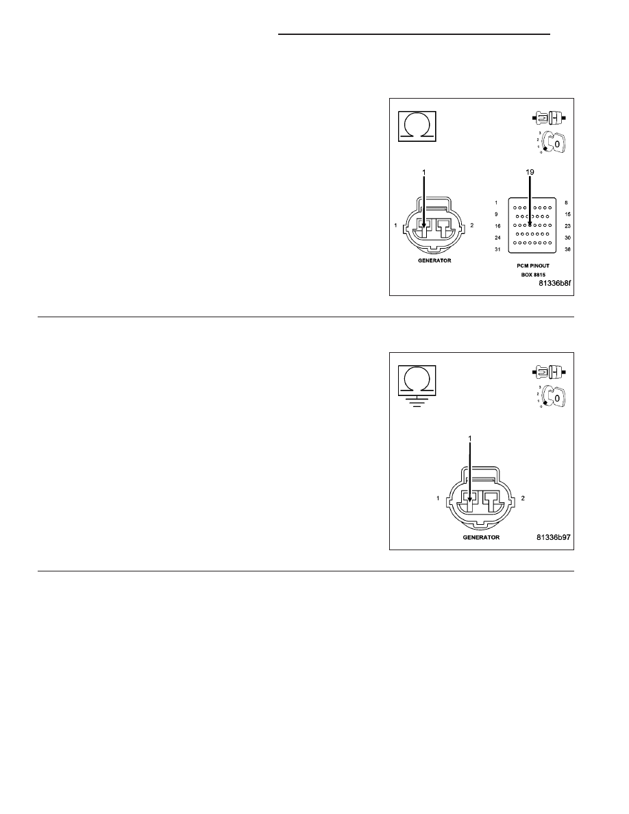
6.
(K20) FIELD CONTROL CIRCUIT OPEN
Turn the ignition off.
CAUTION: Do not probe the PCM harness connectors. Probing
the PCM harness connectors will damage the PCM terminals
resulting in poor terminal to pin connection. Install Miller Special
Tool #8815 to perform diagnosis.
Measure the resistance of the (K20) Gen Field Control circuit from the
Generator Field harness connector to the appropriate terminal of spe-
cial tool #8815.
Is the resistance below 5.0 ohms?
Yes
>> Go To 7
No
>> Repair the open in the (K20) Gen Field Control circuit.
Perform POWERTRAIN VERIFICATION TEST. (Refer to 9
- ENGINE - STANDARD PROCEDURE)
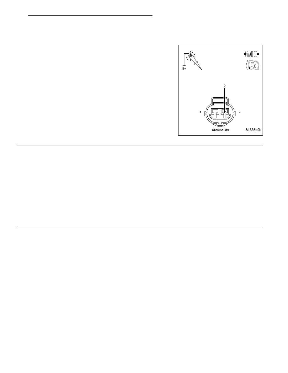
7.
(K20) GEN FIELD CONTROL CIRCUIT SHORTED TO GROUND
Measure the resistance between ground and the (K20) Gen Field Con-
trol circuit in the Generator Field harness connector.
Is the resistance below 100 ohms?
Yes
>> Repair the short to ground in the (K20) Gen Field Control
circuit.
Perform POWERTRAIN VERIFICATION TEST. (Refer to 9
- ENGINE - STANDARD PROCEDURE)
No
>> Go To 8
9 - 706
ENGINE ELECTRICAL DIAGNOSTICS
ND
P2503-CHARGING SYSTEM OUTPUT LOW (CONTINUED)
8.
(Z20) GROUND CIRCUIT OPEN
Using a 12-volt test light connected to battery voltage, probe the (Z20)
Ground circuit in the Generator Field harness connector.
Does the test light illuminate brightly?
Yes
>> Go To 9
No
>> Repair the open in the (Z20) Generator Ground circuit.
Perform POWERTRAIN VERIFICATION TEST. (Refer to 9
- ENGINE - STANDARD PROCEDURE)
9.
PCM
NOTE: Before continuing, check the PCM harness connector terminals for corrosion, damage, or terminal
push out. Repair as necessary.
Using the schematics as a guide, inspect the wire harness and connectors. Pay particular attention to all Power and
Ground circuits.
Were there any problems found?
Yes
>> Repair as necessary.
Perform POWERTRAIN VERIFICATION TEST. (Refer to 9 - ENGINE - STANDARD PROCEDURE)
No
>> Replace and program the Powertrain Control Module per Service Information.
Perform POWERTRAIN VERIFICATION TEST. (Refer to 9 - ENGINE - STANDARD PROCEDURE)
ND
ENGINE ELECTRICAL DIAGNOSTICS
9 - 707

U0001-CAN C BUS
9 - 708
ENGINE ELECTRICAL DIAGNOSTICS
ND
U0001-CAN C BUS (CONTINUED)
For the Engine circuit diagram (Refer to 9 - ENGINE - SCHEMATICS AND DIAGRAMS).
For a complete wiring diagram Refer to Section 8W.
•
When Monitored:
Ignition run time is greater than 1 second. Battey voltage between 9 and 16 volts. Engine run time greater than
3 seconds.
•
Set Condition:
The PCM loses communication over the CAN C Bus circuit. The circuit is continuously monitored.
Possible Causes
CAN C BUS FAILURE OPEN OR SHORTED CONDITION
PCM
Always perform the Pre-Diagnostic Troubleshooting procedure before proceeding. (Refer to 9 - ENGINE -
DIAGNOSIS AND TESTING).
Refer to 8 - ELECTRICAL/ELECTRONIC CONTROL MODULES - DIAGNOSIS AND TESTING for diagnostic
procedures and for further possible causes.
Diagnostic Test
1.
ACTIVE DTC
Ignition on, engine not running.
With a scan tool, read FCM DTCs.
Is the DTC active at this time?
Yes
>> Refer to 8 - ELECTRICAL/ELECTRONIC CONTROL MODULES - DIAGNOSIS AND TESTING for diag-
nostic procedures and for further possible causes.
No
>> Refer to the INTERMITTENT CONDITION Diagnostic Procedure.
Perform POWERTRAIN VERIFICATION TEST. (Refer to 9 - ENGINE - STANDARD PROCEDURE)
ND
ENGINE ELECTRICAL DIAGNOSTICS
9 - 709
Нет комментариевНе стесняйтесь поделиться с нами вашим ценным мнением.
Текст