Dodge Dakota (ND). Manual — part 791
P2503-CHARGING SYSTEM OUTPUT LOW
9 - 702
ENGINE ELECTRICAL DIAGNOSTICS
ND
P2503-CHARGING SYSTEM OUTPUT LOW (CONTINUED)
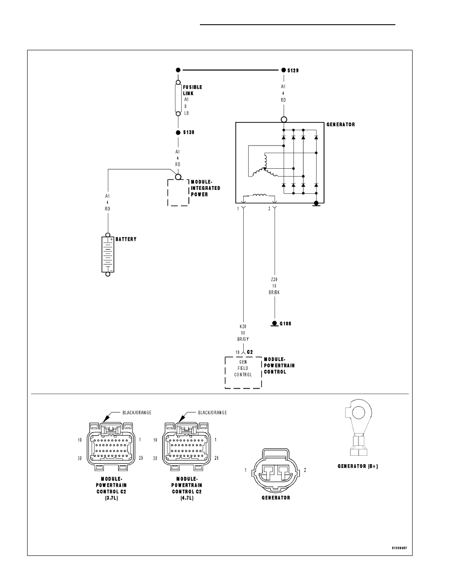
For the Engine circuit diagram (Refer to 9 - ENGINE - SCHEMATICS AND DIAGRAMS).
For a complete wiring diagram Refer to Section 8W.
•
When Monitored:
The engine running. The engine speed greater than 1157 RPM.
•
Set Condition:
The battery sensed voltage is 1 volt below the charging goal for 13.47 seconds. The PCM senses the battery
voltage turns off the field driver and senses the battery voltage again. If the voltages are the same, the code
is set. One Trip Fault. Three good trips to turn off the MIL.
Possible Causes
EXCESSIVE RESISTANCE IN THE (A1) BATTERY POSITIVE CIRCUIT
EXCESSIVE RESISTANCE IN THE CASE GROUND
(K20) GEN FIELD CONTROL CIRCUIT SHORTED TO VOLTAGE
(K20) GEN FIELD CONTROL CIRCUIT OPEN
(K20) GEN FIELD CONTROL CIRCUIT SHORTED TO GROUND
(Z20) GEN GROUND CIRCUIT OPEN
GENERATOR
PCM
Always perform the Pre-Diagnostic Troubleshooting procedure before proceeding. (Refer to 9 - ENGINE -
DIAGNOSIS AND TESTING).
Diagnostic Test
1.
ACTIVE DTC
NOTE: Inspect the vehicle for aftermarket accessories that may exceed the Generator System output.
Ignition on, engine not running.
NOTE: The battery must be fully charged.
NOTE: The Generator belt tension and condition must be checked before continuing.
With a scan tool, read DTCs.
With a scan tool, erase DTCs.
Start the engine.
Allow the idle to stabilize.
With the scan tool, read DTCs.
Is the DTC active at this time?
Yes
>> Go To 2
No
>> Refer to the INTERMITTENT CONDITION Diagnostic Procedure.
Perform POWERTRAIN VERIFICATION TEST. (Refer to 9 - ENGINE - STANDARD PROCEDURE)
ND
ENGINE ELECTRICAL DIAGNOSTICS
9 - 703
P2503-CHARGING SYSTEM OUTPUT LOW (CONTINUED)
2.
(A1) FUSED B+ CIRCUIT HIGH RESISTANCE
WARNING: When the engine is operating, do not stand in direct
line with the fan. Do not put your hands near the pulleys, belts, or
fan. Do not wear loose clothing. Failure to follow these instruc-
tions can result in personal injury or death.
Ignition on, engine not running.
NOTE: Make sure all wires are clear of the engine’s moving parts.
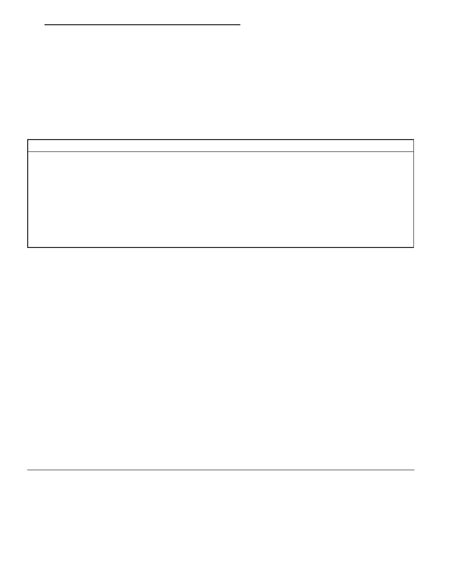
Measure the voltage between the Generator B+ Output Terminal and
the Battery+ Post.
Start the engine.
Is the voltage above 0.4 of a volt?
Yes
>> Repair the excessive resistance in the (A1) Battery posi-
tive circuit between the Generator and Battery.
Perform POWERTRAIN VERIFICATION TEST. (Refer to 9
- ENGINE - STANDARD PROCEDURE)
No
>> Go To 3
3.
EXCESSIVE RESISTANCE IN THE CASE GROUND
WARNING: When the engine is operating, do not stand in direct line with the fan. Do not put your hands
near the pulleys, belts, or fan. Do not wear loose clothing. Failure to follow these instructions can result in
personal injury or death.
Start the engine.
Warm the engine to operating temperature.
NOTE: Make sure all wires are clear of the engine’s moving parts.
Measure the voltage between the Generator Case and Battery ground post.
Is the voltage above 0.1 of a volt?
Yes
>> Repair the excessive resistance in the Generator Case Ground.
Perform POWERTRAIN VERIFICATION TEST. (Refer to 9 - ENGINE - STANDARD PROCEDURE)
No
>> Go To 4
9 - 704
ENGINE ELECTRICAL DIAGNOSTICS
ND
P2503-CHARGING SYSTEM OUTPUT LOW (CONTINUED)
4.
GENERATOR OPERATION
Turn the ignition off.
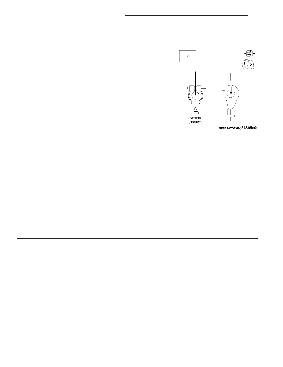
Disconnect the Generator Field harness connector.
Using a 12-volt test light, jump across the Generator Field harness
connector.
Ignition on, engine not running.
With a scan tool, actuate the Generator Field Driver.
Does the test light illuminate brightly and flash on and off?
Yes
>> Replace the Generator.
Perform POWERTRAIN VERIFICATION TEST. (Refer to 9
- ENGINE - STANDARD PROCEDURE)
No
>> Go To 5
5.
(K20) GEN FIELD CONTROL CIRCUIT SHORTED TO BATTERY VOLTAGE
Turn the ignition off.
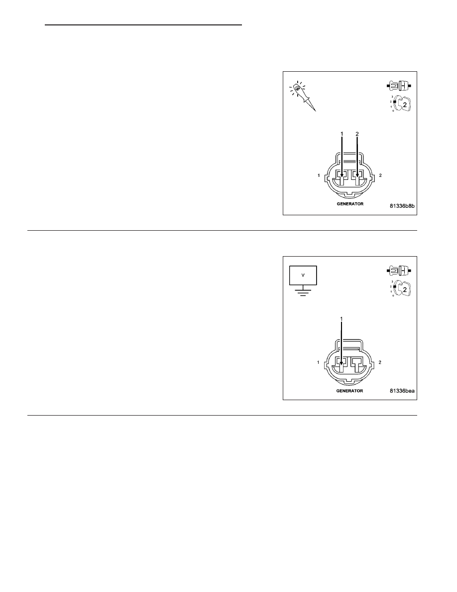
Disconnect the C2 PCM harness connector.
Ignition on, engine not running.
Measure the voltage on the (K20) Gen Field Control circuit in the Gen-
erator Field harness connector.
Is the voltage above 1.0 volt?
Yes
>> Repair the short to battery voltage in the (K20) Gen Field
Control circuit.
Perform POWERTRAIN VERIFICATION TEST. (Refer to 9
- ENGINE - STANDARD PROCEDURE)
No
>> Go To 6
ND
ENGINE ELECTRICAL DIAGNOSTICS
9 - 705
Нет комментариевНе стесняйтесь поделиться с нами вашим ценным мнением.
Текст