Dodge Dakota (ND). Manual — part 1258
B105F–CLIMATE CONTROL MOTOR(S) COMMON 1 CONTROL CIRCUIT LOW
24 - 30
HVAC - ELECTRICAL DIAGNOSTICS
ND
B105F–CLIMATE CONTROL MOTOR(S) COMMON 1 CONTROL CIRCUIT LOW (CONTINUED)
For the Manual Temperature Control (MTC) circuit diagram (Refer to 24 - HEATING & AIR CONDITIONING - SCHE-
MATICS AND DIAGRAMS).
For a complete wiring diagram Refer to Section 8W.
Theory of Operation
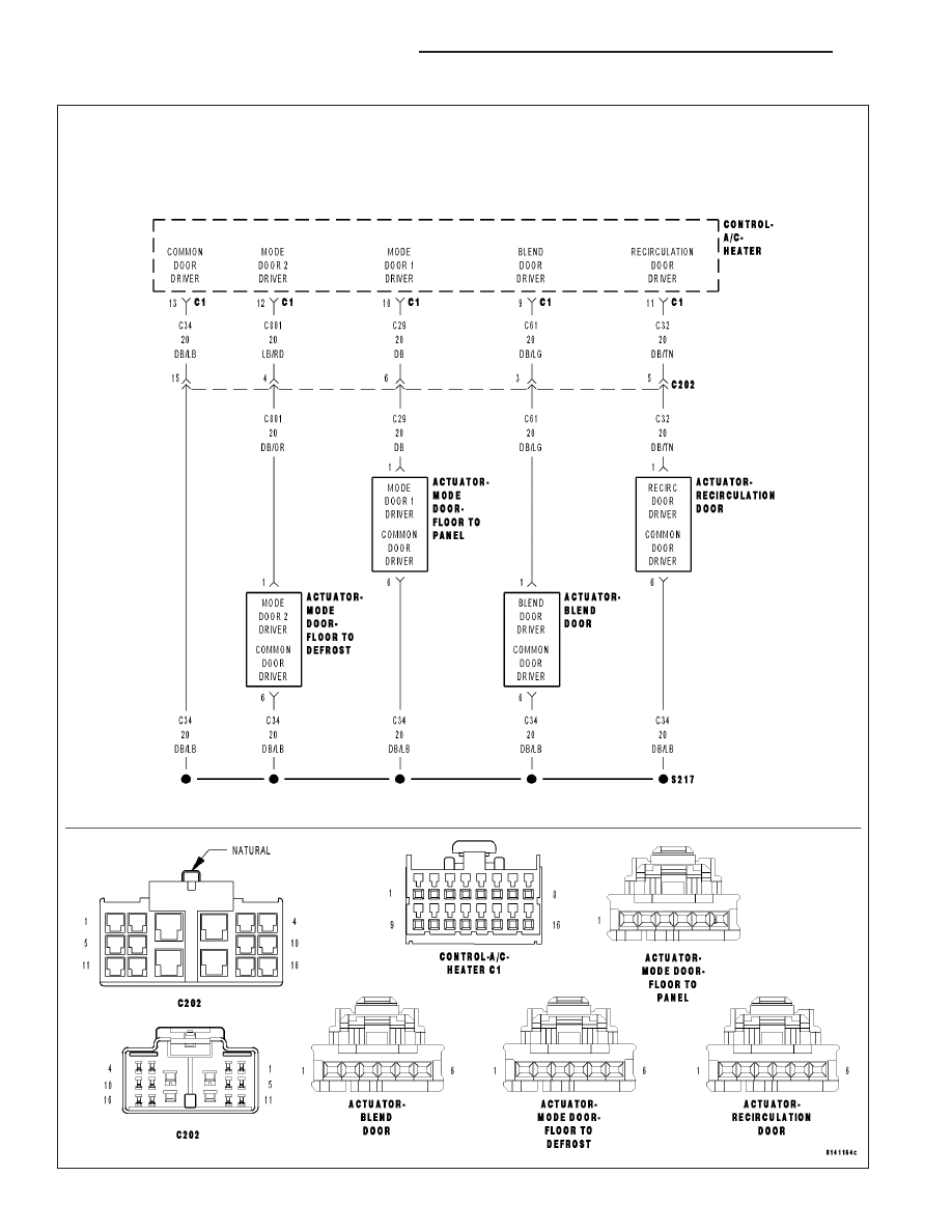
The A/C Heater Control drives the Blend Door Actuator via the (C61) Blend Door Driver circuit and the (C34) Com-
mon Door Driver circuit. The A/C Heater Control drives the Mode Door 1 (Floor to Panel) Actuator via the (C29)
Mode Door 1 Driver circuit and the (C34) Common Door Driver circuit. The A/C Heater Control drives the Mode
Door 2 (Floor to Defrost) Actuator via the (C801) Mode Door 2 Driver circuit and the (C34) Common Door Driver
circuit. The A/C Heater Control drives the Recirculation Door Actuator via the (C32) Recirculation Door Driver circuit
and the (C34) Common Door Driver circuit. All of the door actuators share the (C34) Common Door Driver circuit.
Inside the A/C Heater Control, each door actuator has its own unique driver, but all share a single common door
driver circuit. Due to the shared circuitry similar DTCs can set at the same time for multiple actuators depending
upon the type of short, its location, and the direction the actuator is moving when the short is present.
•
When Monitored:
When the Actuator DTC Detection Test is executed.
•
Set Condition:
If the (C34) Common Door Driver circuit is shorted to ground.
Possible Causes
(C34) COMMON DOOR DRIVER CIRCUIT SHORTED TO GROUND
(C34) COMMON DOOR DRIVER CIRCUIT SHORTED TO OTHER DOOR DRIVER CIRCUIT(S)
BLEND DOOR ACTUATOR
MODE DOOR 1 (FLOOR TO PANEL) ACTUATOR
MODE DOOR 2 (FLOOR TO DEFROST) ACTUATOR
RECIRCULATION DOOR ACTUATOR
A/C HEATER CONTROL
Diagnostic Test
1.
CHECK (C34) COMMON DOOR DRIVER CIRCUIT FOR A
SHORT TO GROUND
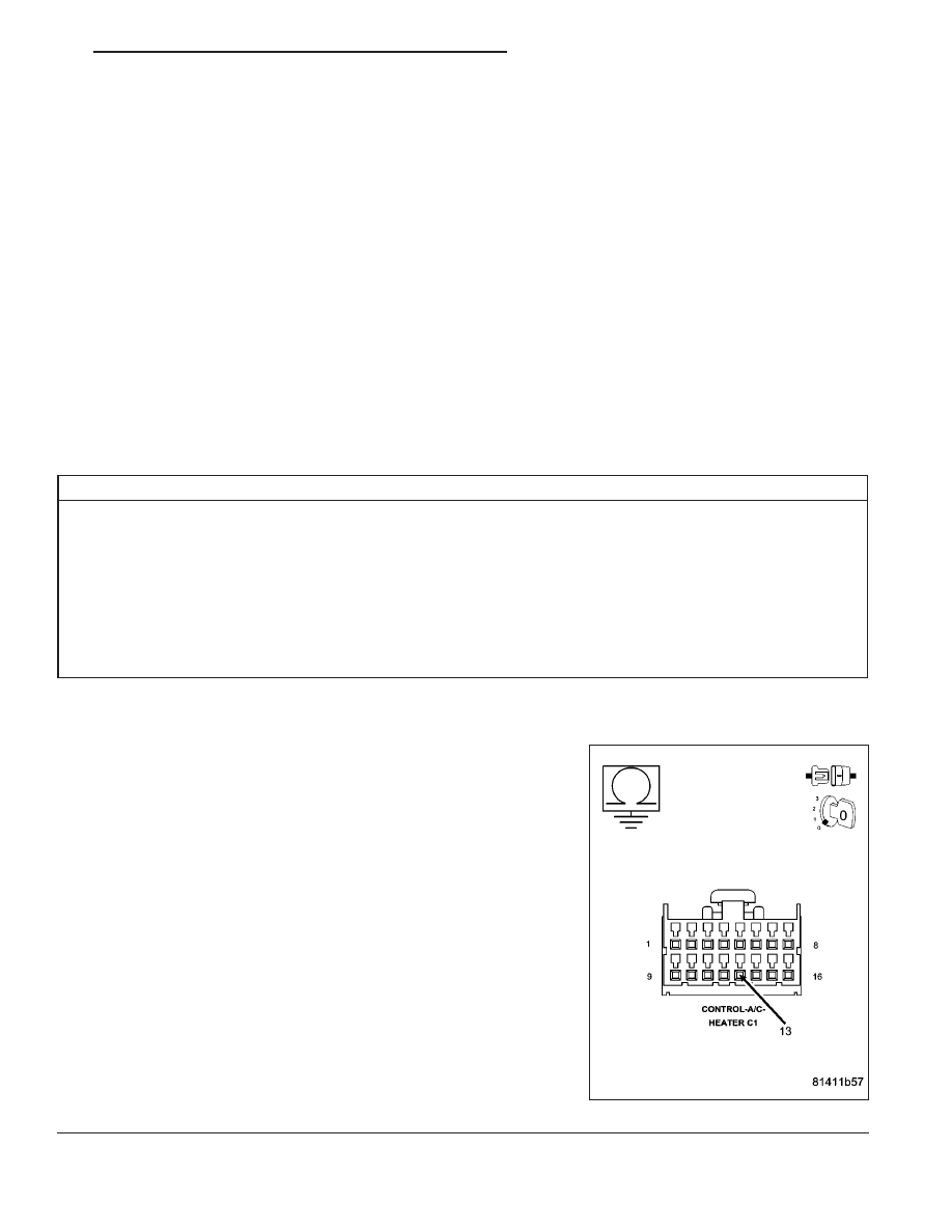
Turn the ignition off.
Disconnect the A/C Heater Control C1 harness connector.
Measure the resistance of the (C34) Common Door Driver circuit
between ground and the A/C Heater Control C1 harness connector.
Is the resistance below 10k ohms?
Yes
>> Repair the (C34) Common Door Driver circuit for a short to
ground.
Perform BODY VERIFICATION TEST - VER 1. (Refer to 8
-
ELECTRICAL/ELECTRONIC
CONTROL
MODULES/
FRONT CONTROL MODULE - DIAGNOSIS AND TEST-
ING).
No
>> Go To 2
ND
HVAC - ELECTRICAL DIAGNOSTICS
24 - 31
B105F–CLIMATE CONTROL MOTOR(S) COMMON 1 CONTROL CIRCUIT LOW (CONTINUED)
2.
CHECK BLEND DOOR ACTUATOR CIRCUIT RESISTANCE
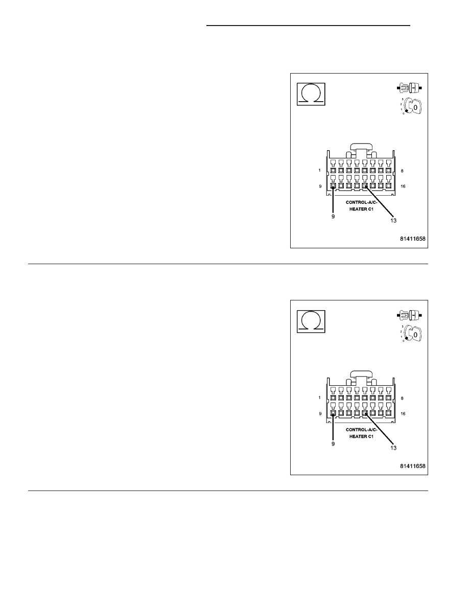
Measure the resistance between the (C61) Blend Door Driver circuit
and the (C34) Common Door Driver circuit in the A/C Heater Control
C1 harness connector.
Is the resistance below 20 ohms?
Yes
>> Go To 3
No
>> Go To 4
3.
CHECK (C61) BLEND DOOR DRIVER CIRCUIT FOR A SHORT TO (C34) COMMON DOOR DRIVER
CIRCUIT
Disconnect the Blend Door Actuator harness connector.
Measure the resistance between the (C61) Blend Door Driver circuit
and the (C34) Common Door Driver circuit in the A/C Heater Control
C1 harness connector.
Is the resistance below 10k ohms?
Yes
>> Repair the (C61) Blend Door Driver Circuit for a short to
the (C34) Common Door Driver circuit.
Perform BODY VERIFICATION TEST - VER 1. (Refer to 8
-
ELECTRICAL/ELECTRONIC
CONTROL
MODULES/
FRONT CONTROL MODULE - DIAGNOSIS AND TEST-
ING).
No
>> Replace the Blend Door Actuator in accordance with the
Service Information.
Perform BODY VERIFICATION TEST - VER 1. (Refer to 8
-
ELECTRICAL/ELECTRONIC
CONTROL
MODULES/
FRONT
CONTROL
MODULE
-
DIAGNOSIS
AND
TESTING).
24 - 32
HVAC - ELECTRICAL DIAGNOSTICS
ND
B105F–CLIMATE CONTROL MOTOR(S) COMMON 1 CONTROL CIRCUIT LOW (CONTINUED)
4.
CHECK MODE DOOR 1 (FLOOR TO PANEL) ACTUATOR CIRCUIT RESISTANCE
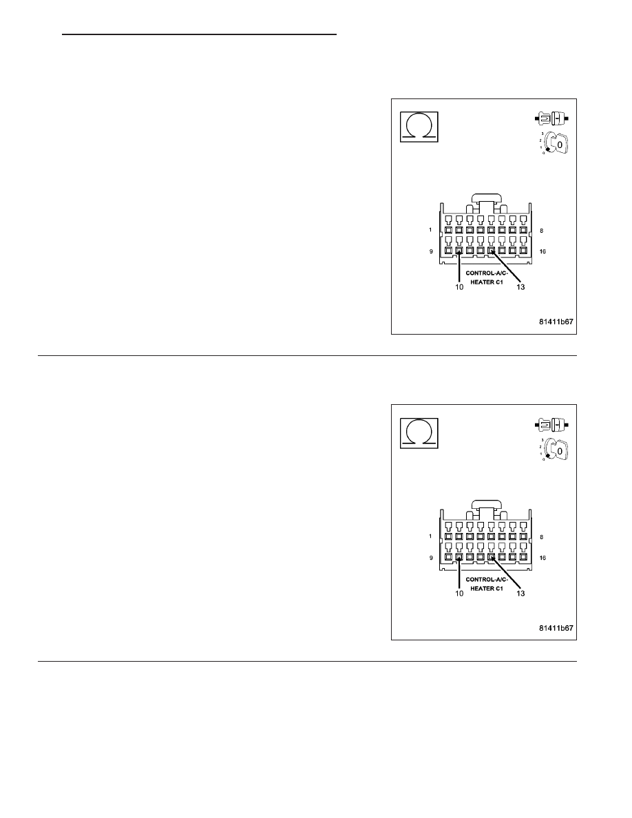
Measure the resistance between the (C29) Mode Door 1 Driver circuit
and the (C34) Common Door Driver circuit in the A/C Heater Control
C1 harness connector.
Is the resistance below 20 ohms?
Yes
>> Go To 5
No
>> Go To 6
5.
CHECK (C29) MODE DOOR 1 DRIVER CIRCUIT FOR A SHORT TO (C34) COMMON DOOR DRIVER
CIRCUIT
Disconnect the Mode Door 1 (Floor to Panel) Actuator harness con-
nector.
Measure the resistance between the (C29) Mode Door 1 Driver circuit
and the (C34) Common Door Driver circuit in the A/C Heater Control
C1 harness connector.
Is the resistance below 10k ohms?
Yes
>> Repair the (C29) Mode Door 1 Driver Circuit for a short to
the (C34) Common Door Driver circuit.
Perform BODY VERIFICATION TEST - VER 1. (Refer to 8
-
ELECTRICAL/ELECTRONIC
CONTROL
MODULES/
FRONT CONTROL MODULE - DIAGNOSIS AND TEST-
ING).
No
>> Replace the Mode Door 1 (Floor to Panel) Actuator in
accordance with the Service Information.
Perform BODY VERIFICATION TEST - VER 1. (Refer to 8
-
ELECTRICAL/ELECTRONIC
CONTROL
MODULES/
FRONT
CONTROL
MODULE
-
DIAGNOSIS
AND
TESTING).
ND
HVAC - ELECTRICAL DIAGNOSTICS
24 - 33
Нет комментариевНе стесняйтесь поделиться с нами вашим ценным мнением.
Текст