Dodge Dakota (ND). Manual — part 1292
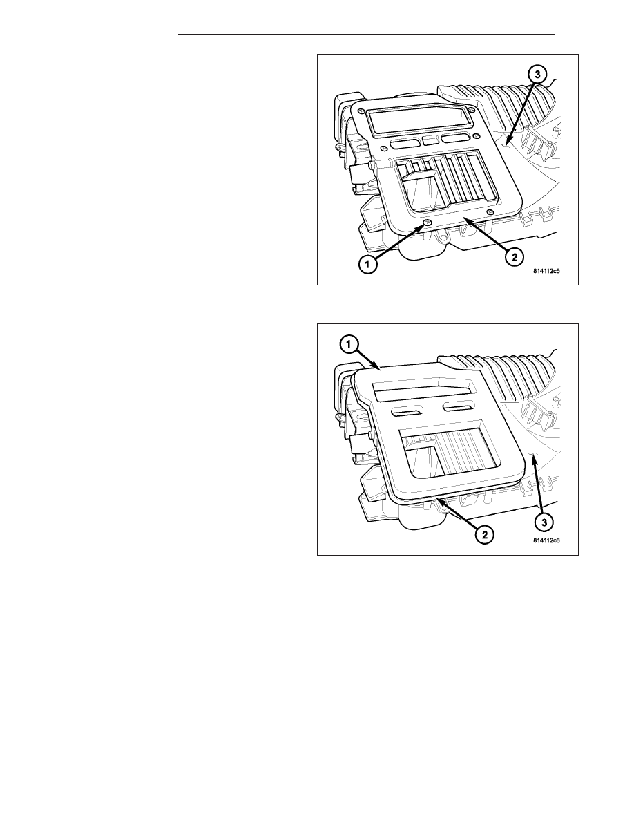
14. Install the panel/defrost outlet (2) onto the top of
the HVAC housing (3).
15. Install the six screws (1) that secure the panel/de-
frost outlet to the HVAC housing. Tighten the
screws to 2 N·m (17 in. lbs.).
NOTE: If the seal for the panel/defrost outlet is
deformed or damaged, the seal must be replaced.
16. Install the foam seal (1) onto the panel/defrost
outlet (2) located on the top of the HVAC housing
(3).
24 - 166
DISTRIBUTION
ND
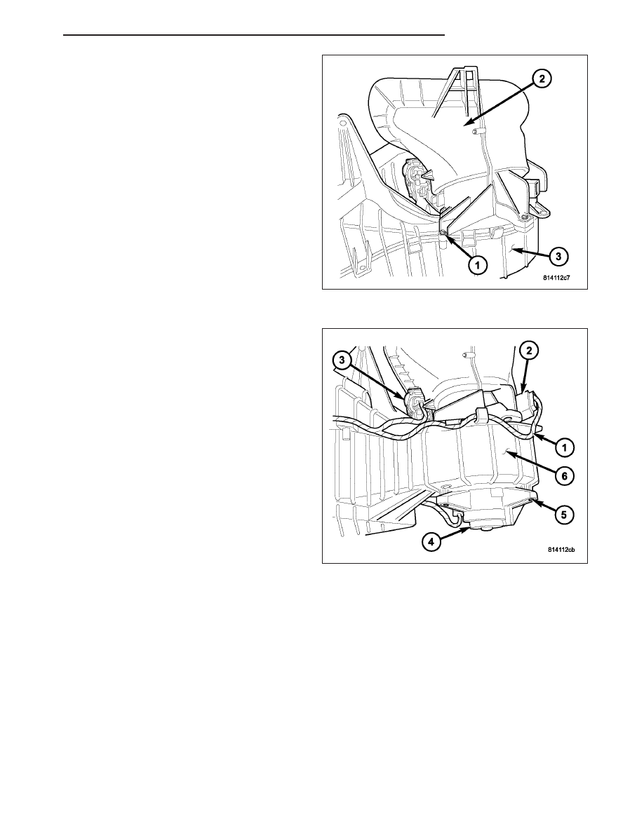
17. Position the air inlet housing (2) onto the top of
the HVAC housing (3).
NOTE: If the foam seal on the air inlet housing is
deformed or damaged, the seal must be replaced.
18. Install the four screws (1) that secure the air inlet
housing to the top of the HVAC housing. Tighten
the screws to 2 N·m (17 in. lbs.).
19. Position the blower motor (4) into the HVAC hous-
ing (6).
20. Install the three screws (5) that secure the blower
motor to the HVAC housing. Tighten the screws to
2 N·m (17 in. lbs.).
NOTE: Make sure that all HVAC wire harness leads
are correctly routed through the wiring retainers.
21. Install the HVAC wire harness (1) onto the HVAC
housing.
22. Connect the HVAC wire harness to the blower
motor resistor (2), recirculation door actuator (3)
and the blower motor.
ND
DISTRIBUTION
24 - 167
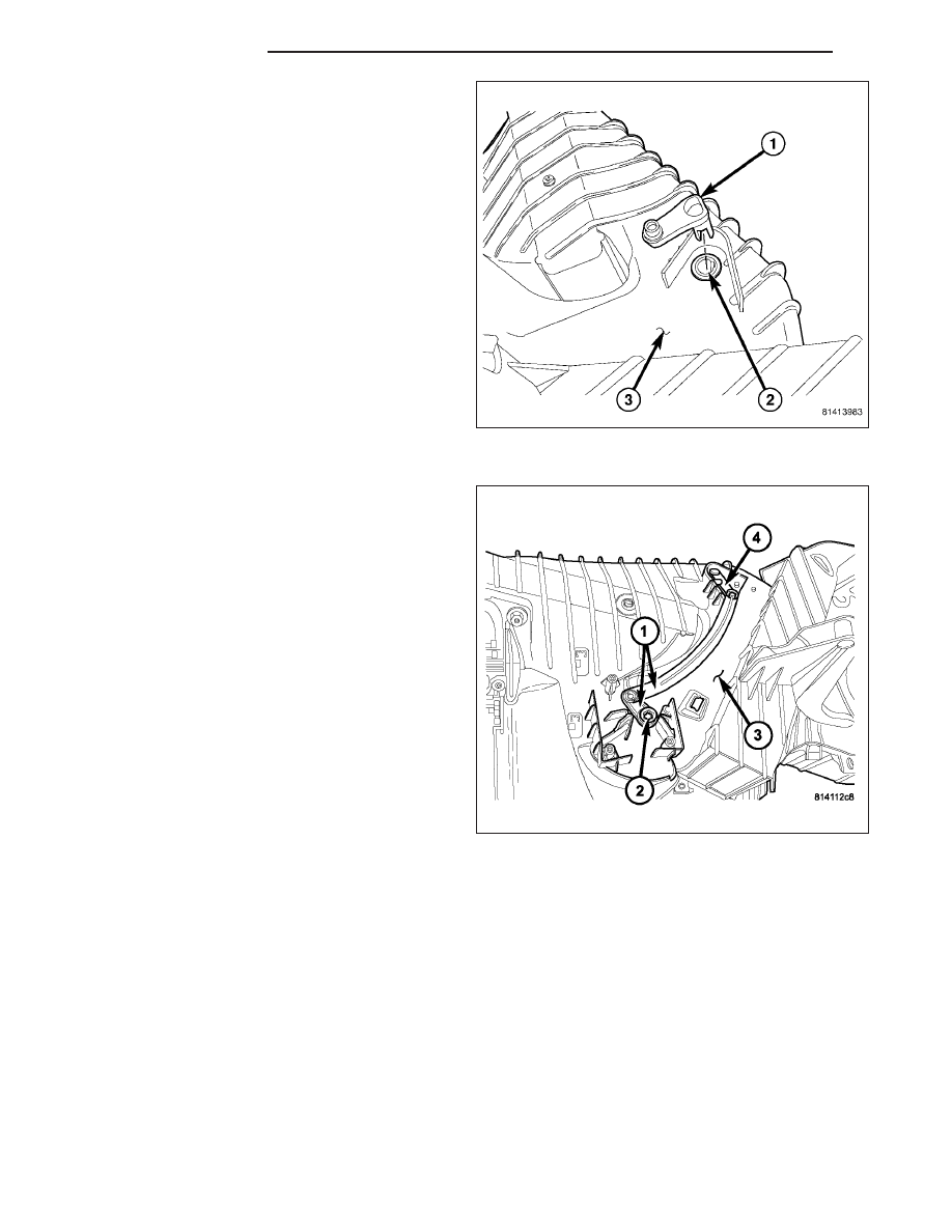
23. Align the blend door pivot lever (1) with the blend-
air door pivot shaft (2) located on the top of the
HVAC housing (3).
NOTE: Make sure that the pivot lever retaining tab
is fully engaged to the blend-air door pivot shaft.
24. Install the blend door pivot lever into the blend-air
door pivot shaft.
25. Connect the lever and linkage rod (1) to the blend
door pivot lever (4) located on the top of the
HVAC housing (3).
26. Install the lever and linkage rod onto the blend
door pivot shaft (2).
24 - 168
DISTRIBUTION
ND
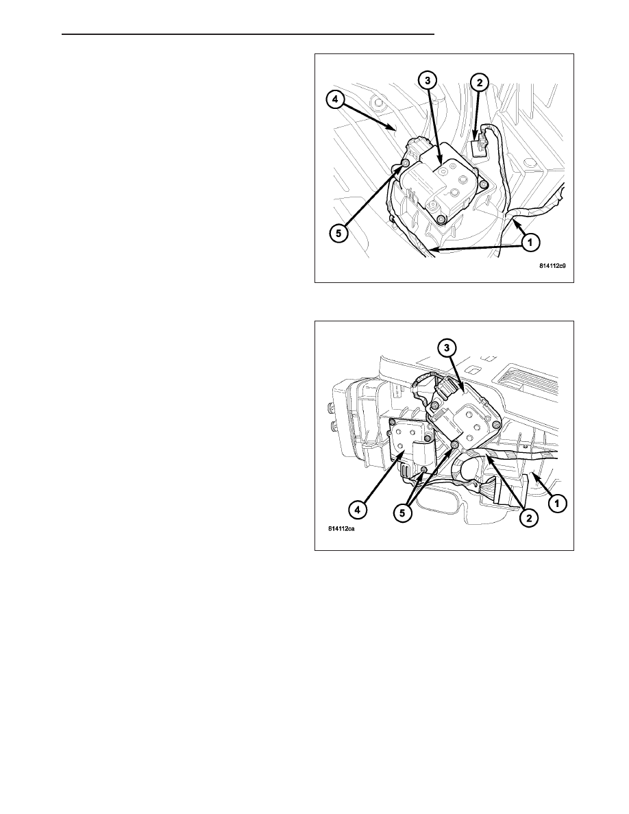
27. Install the evaporator temperature sensor (2) into
the opening located at the top of the HVAC hous-
ing (4).
28. Position the blend door actuator (3) onto the
HVAC housing. If necessary, rotate the actuator
slightly to align the splines on the actuator output
shaft with those on the blend-air door linkage
(Refer to 24 - HEATING & AIR CONDITIONING/
CONTROLS/ACTUATOR-BLEND
DOOR
-
INSTALLATION).
29. Install the three screws (5) that secure the blend
door actuator to the HVAC housing. Tighten the
screws to 2 N·m (17 in. lbs.).
30. Connect the HVAC wire harness (1) to the evap-
orator temperature sensor and the blend door
actuator.
31. Position the mode door actuators (3 and 4) onto
the driver side end of the HVAC housing (1). If
necessary, rotate the actuators slightly to align the
splines on the actuator output shafts with those
on the mode-air doors (Refer to 24 - HEATING &
AIR
CONDITIONING/CONTROLS/ACTUATORS-
MODE DOOR - INSTALLATION).
32. Install the three screws (5) that secure the mode
door actuators to the HVAC housing. Tighten the
screws to 2 N·m (17 in. lbs.).
33. Connect the HVAC wire harness (2) to the mode
door actuator.
34. Install the HVAC housing assembly (Refer to 24 -
HEATING & AIR CONDITIONING/DISTRIBUTION/
HOUSING-HVAC - INSTALLATION).
AIR INLET HOUSING
NOTE: The air inlet housing must be removed from HVAC housing and disassembled for service of the
recirculation-air door.
ND
DISTRIBUTION
24 - 169
Нет комментариевНе стесняйтесь поделиться с нами вашим ценным мнением.
Текст