Dodge Dakota (ND). Manual — part 1281
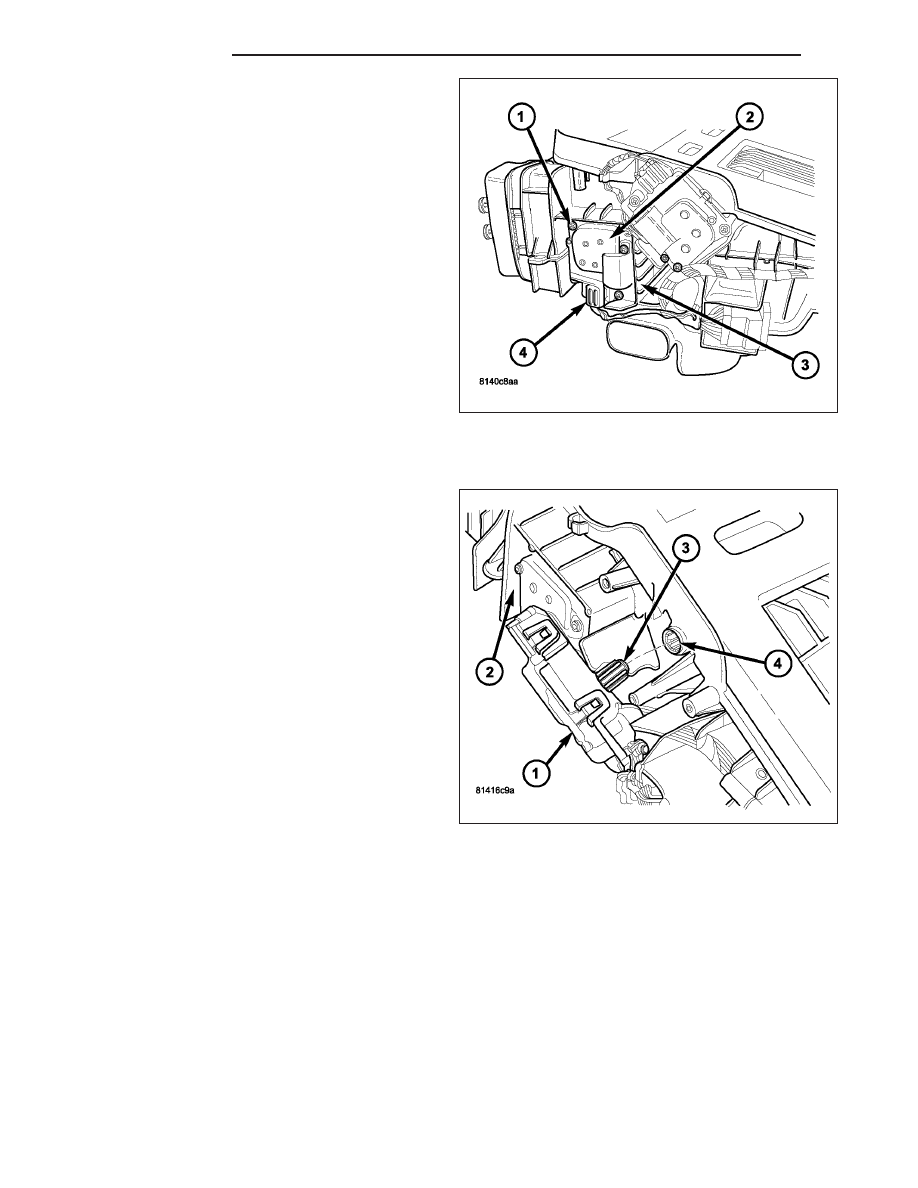
2. Install the three screws (1) that secure the floor/de-
frost door actuator (2) to the HVAC housing (3).
Tighten the screws to 2 N·m (17 in. lbs.).
3. Connect the HVAC wire harness connector (4) to
the floor/defrost door actuator.
4. Reconnect the negative battery cable.
5. Initiate the Actuator Calibration function using a
scan tool. Refer to HVAC System Test, found in 24
- HVAC - Electrical Diagnostics.
PANEL DOOR ACTUATOR
1. Position the panel door actuator (1) onto the driver
side end of the HVAC housing (2). If necessary,
rotate the actuator slightly to align the splines on
the actuator output shaft (3) with those on the
panel door pivot shaft (4).
24 - 122
CONTROLS
ND
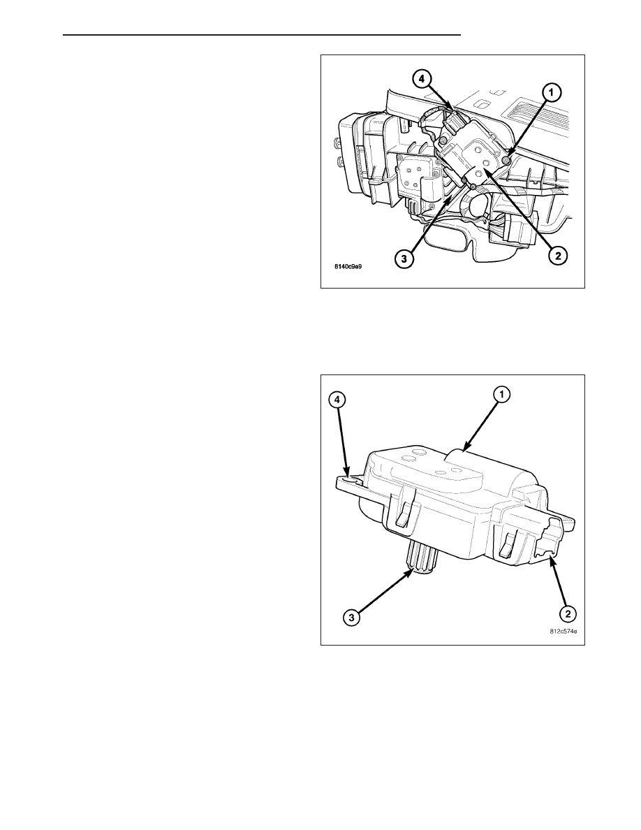
2. Install the three screws (1) that secure the panel
door actuator (2) to the HVAC housing (3). Tighten
the screws to 2 N·m (17 in. lbs.).
3. Connect the HVAC wire harness connector (4) to
the panel door actuator.
4. Reconnect the negative battery cable.
5. Initiate the Actuator Calibration function using a
scan tool. Refer to HVAC System Test, found in 24
- HVAC - Electrical Diagnostics.
ACTUATOR-RECIRCULATION DOOR
DESCRIPTION
The recirculation door actuator (1) is a reversible, 12
volt direct current (DC), servo motor. The recirculation
door actuator is located on the left side of the HVAC
air inlet housing. The recirculation door actuator is
interchangeable with the actuators for the blend-air
doors and the mode-air doors. Each actuator is con-
tained within an identical black molded plastic housing
with an integral wire connector receptacle (2). Each
actuator also has an identical output shaft with splines
(3) that connects it to its door linkage and three inte-
gral mounting tabs (4) that allow the actuator to be
secured to the air inlet housing. The recirculation door
actuator does not require mechanical indexing to the
recirculation-air door, as it is electronically calibrated
by the A/C-heater control.
The recirculation door actuator can be accessed for
serviced by removing the air inlet housing.
OPERATION
The recirculation door actuator is connected to the A/C-heater control through the vehicle electrical system by a
dedicated two-wire lead and connector of the HVAC wire harness. The recirculation door actuator can move the
recirculation-air door in two directions. When the A/C-heater control pulls the voltage on one side of the motor con-
nection high and the other connection low, the recirculation-air door will move in one direction. When the A/C-heater
control reverses the polarity of the voltage to the motor, the recirculation-air door moves in the opposite direction.
When the A/C-heater control makes the voltage to both connections high or both connections low, the recirculation-
air door stops and will not move. The A/C-heater control uses a pulse-count positioning system to monitor the oper-
ation and relative position of the recirculation door actuator and the recirculation-air door. The A/C-heater control
ND
CONTROLS
24 - 123
learns the recirculation-air door stop positions during the calibration procedure and will store a diagnostic trouble
code (DTC) for any problems it detects in the recirculation door actuator circuits.
The recirculation door actuator cannot be adjusted or repaired and, if faulty or damaged, it must be replaced.
The recirculation door actuator is diagnosed using a scan tool. Refer to 24 - HVAC Electrical Diagnostics for more
information.
REMOVAL
WARNING: On vehicles equipped with airbags, disable the airbag system before attempting any steering
wheel, steering column, or instrument panel component diagnosis or service. Disconnect and isolate the
battery negative (ground) cable, then wait two minutes for the airbag system capacitor to discharge before
performing further diagnosis or service. This is the only sure way to disable the airbag system. Failure to
take the proper precautions could result in accidental airbag deployment and possible personal injury or
death.
NOTE: Take the proper precautions to protect the front face of the instrument panel from cosmetic damage
during this service procedure.
1. Disconnect and isolate the negative battery cable.
2. Remove the HVAC assembly (Refer to 24 - HEAT-
ING
&
AIR
CONDITIONING/DISTRIBUTION/
HOUSING-HVAC - REMOVAL).
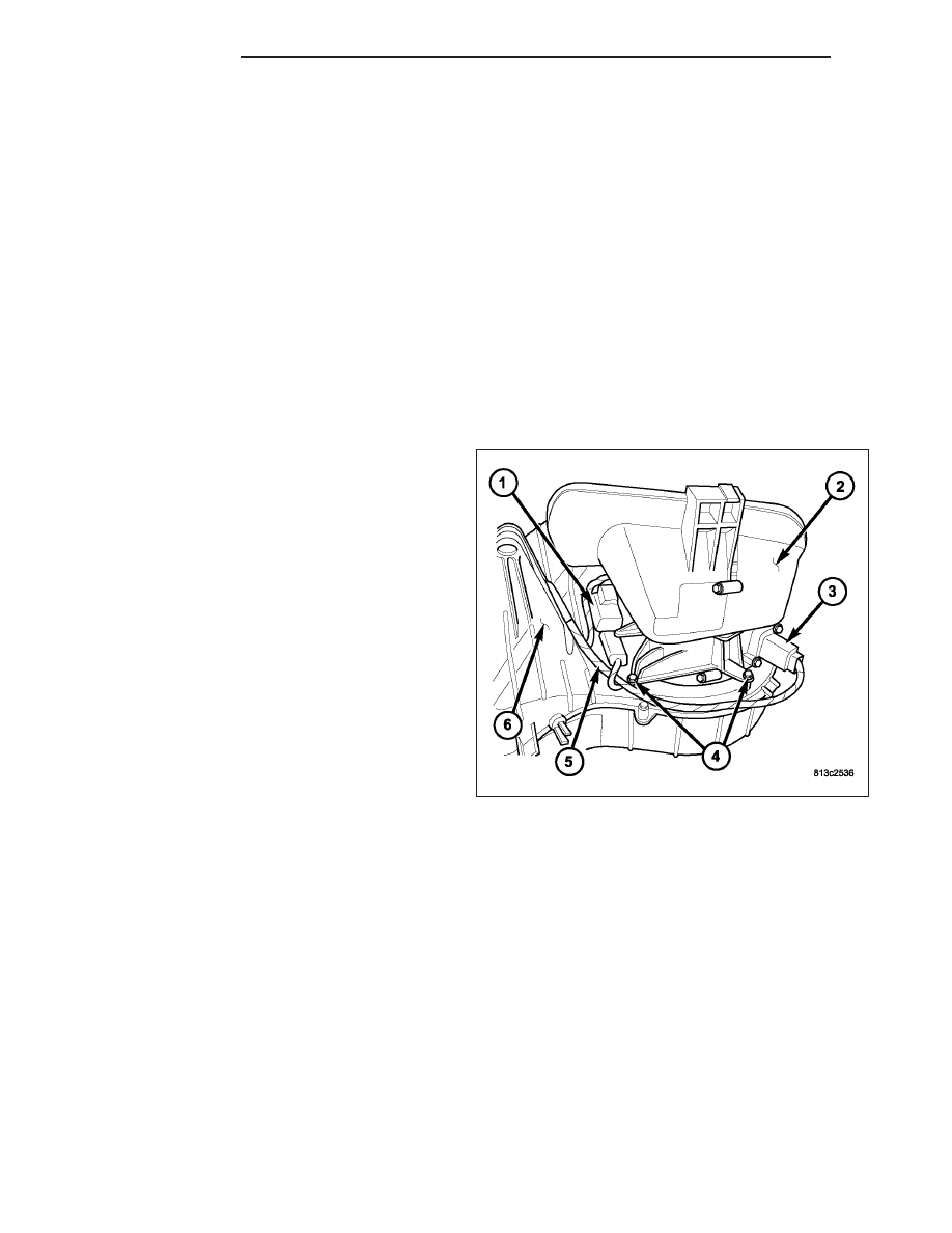
3. Disconnect the HVAC wire harness (5) from the
recirculation door actuator (1) and the blower motor
resistor (3).
4. Remove the four screws (4) that secure the air inlet
housing (2) to the top of the HVAC housing (6).
5. Remove the air inlet housing from the HVAC hous-
ing and place it on a workbench.
24 - 124
CONTROLS
ND
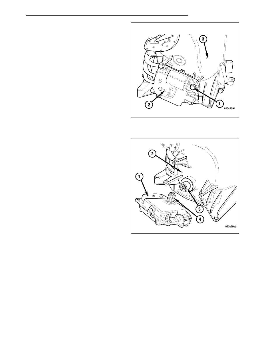
6. Remove the three screws (1) that secure the recir-
culation door actuator (2) to the air inlet housing
(3).
7. Remove the recirculation door actuator from the air
inlet housing.
INSTALLATION
1. Position the recirculation door actuator (1) onto the
air inlet housing (2). If necessary, rotate the actua-
tor slightly to align the splines in the recirculation-
air door pivot shaft (3) with those on the actuator
output shaft (4).
ND
CONTROLS
24 - 125
Нет комментариевНе стесняйтесь поделиться с нами вашим ценным мнением.
Текст