Dodge Dakota (ND). Manual — part 1279

SPECIFICATIONS
A/C SYSTEM
Item
Description
Notes
A/C Compressor
Denso 10S17
ND-8 PAG oil
Freeze–up Control
Evaporator Temperature Sensor
HVAC housing mounted - input to
A/C-heater control
Low psi Control
A/C Pressure Transducer
Liquid line mounted - input to FCM -
opens below 28 psi, closes above
34 psi
High psi Control
A/C Pressure Transducer
Liquid line mounted - input to FCM -
opens above 460 psi, closed below
290 psi
Refrigerant Charge Capacity
Refer to the Underhood
Specification Label in the engine
compartment
R-134a refrigerant
A/C Clutch Coil Draw
3.3 amps
@ 12V ± 0.5V @ 21° C (70° F)
A/C Clutch Coil Resistance
3.6 ± 0.2 ohms
When measured across coil lead
connector
A/C Clutch Air Gap
0.35 - 0.60 mm (0.014 - 0.024 in.)
24 - 114
HVAC - SERVICE INFORMATION
ND
SPECIAL TOOLS
A/C SYSTEM
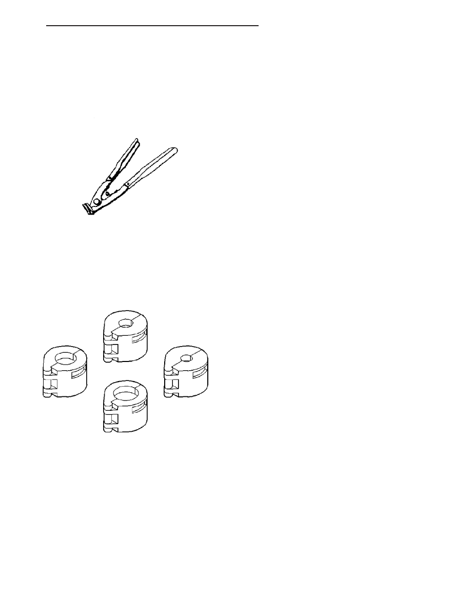
Snap Ring Pliers C-4574 are required to service the
A/C clutch and field coil.
A/C Line Disconnect Tools 7193 are required to service
the A/C liquid line and the A/C accumulator.
A/C Line Disconnect Tools 7193
ND
HVAC - SERVICE INFORMATION
24 - 115
CONTROLS
TABLE OF CONTENTS
page
page
ACTUATOR-BLEND DOOR
. . . . . . . . . . . . . . . . . . . . . . . . 117
. . . . . . . . . . . . . . . . . . . . . . . . . . 117
. . . . . . . . . . . . . . . . . . . . . . . . . . . . 117
. . . . . . . . . . . . . . . . . . . . . . . . 118
ACTUATOR-MODE DOOR
. . . . . . . . . . . . . . . . . . . . . . . . 119
. . . . . . . . . . . . . . . . . . . . . . . . . . 119
. . . . . . . . . . . . . . . . . . . . . . . . . . . . 120
. . . . . . . . . . . . . . . . . . . . . . . . 121
ACTUATOR-RECIRCULATION DOOR
. . . . . . . . . . . . . . . . . . . . . . . . 123
. . . . . . . . . . . . . . . . . . . . . . . . . . 123
. . . . . . . . . . . . . . . . . . . . . . . . . . . . 124
. . . . . . . . . . . . . . . . . . . . . . . . 125
CLUTCH-A/C COMPRESSOR
. . . . . . . . . . . . . . . . . . . . . . . . 127
. . . . . . . . . . . . . . . . . . . . . . . . . . 127
. . . . . . . . . . . . . . . . 129
. . . . . . . . . . . . . . . . . . . . . . . . . . . . 129
. . . . . . . . . . . . . . . . . . . . . . . . 132
CONTROL-A/C HEATER
. . . . . . . . . . . . . . . . . . . . . . . . 134
. . . . . . . . . . . . . . . . . . . . . . . . . . . . 135
. . . . . . . . . . . . . . . . . . . . . . . . 135
RELAY-A/C CLUTCH
. . . . . . . . . . . . . . . . . . . . . . . . 136
. . . . . . . . . . . . . . . . . . . . . . . . . . 136
. . . . . . . . . . . . . . . . . . . . . . . . . . . . 137
. . . . . . . . . . . . . . . . . . . . . . . . 137
RESISTOR-BLOWER MOTOR
. . . . . . . . . . . . . . . . . . . . . . . . 138
. . . . . . . . . . . . . . . . . . . . . . . . . . 138
. . . . . . . . . . . . . . . . . . . . . . . . . . . . 139
. . . . . . . . . . . . . . . . . . . . . . . . 139
SENSOR-AMBIENT AIR TEMPERATURE
. . . . . . . . . . . . . . . . . . . . . . . . 140
. . . . . . . . . . . . . . . . . . . . . . . . . . 140
. . . . . . . . . . . . . . . . . . . . . . . . . . . . 140
. . . . . . . . . . . . . . . . . . . . . . . . 141
SENSOR-EVAPORATOR TEMPERATURE
. . . . . . . . . . . . . . . . . . . . . . . . 141
. . . . . . . . . . . . . . . . . . . . . . . . . . 141
. . . . . . . . . . . . . . . . . . . . . . . . . . . . 142
. . . . . . . . . . . . . . . . . . . . . . . . 143
TRANSDUCER-A/C PRESSURE
. . . . . . . . . . . . . . . . . . . . . . . . 143
. . . . . . . . . . . . . . . . . . . . . . . . . . 143
. . . . . . . . . . . . . . . . . . . . . . . . . . . . 144
. . . . . . . . . . . . . . . . . . . . . . . . 145
24 - 116
CONTROLS
ND
ACTUATOR-BLEND DOOR
DESCRIPTION
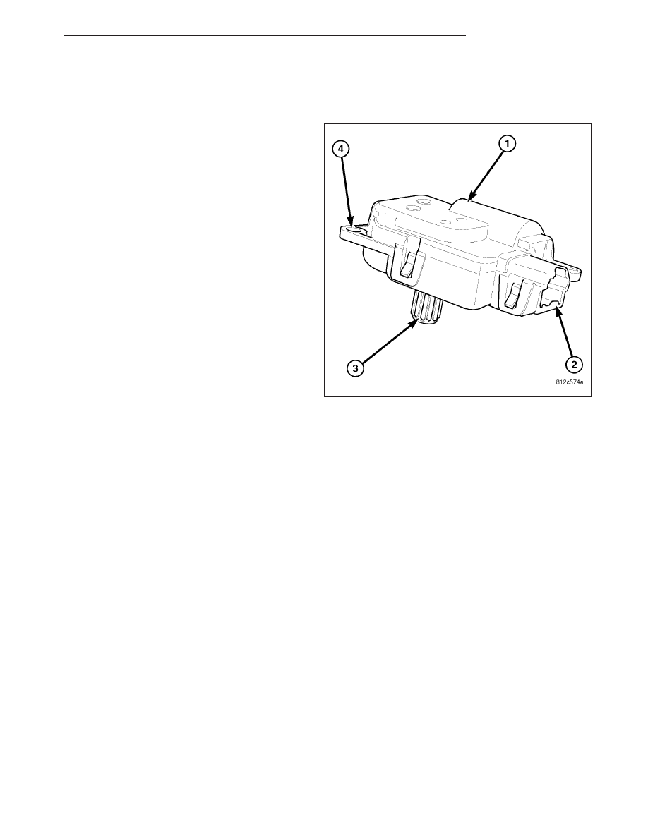
The blend door actuator (1) is a reversible, 12 volt
direct current (DC), servo motor. The blend door
actuator is located on the top of the HVAC housing.
The blend door actuator is interchangeable with the
actuators for the mode-air and recirculation-air doors.
Each actuator is contained within an identical black
molded plastic housing with an integral wire connector
receptacle (2). Each actuator also has an identical
output shaft with splines (3) that connects it to its
respective door linkage and three integral mounting
tabs (4) that allow the actuator to be secured to the
HVAC housing. The blend door actuator does not
require mechanical indexing to the blend-air doors, as
it is electronically calibrated by the A/C-heater control.
The blend door actuator can be accessed for serviced
by removing the instrument panel.
OPERATION
The blend door actuator is connected to the A/C-heater control through the vehicle electrical system by a dedicated
two-wire lead and connector of the HVAC wire harness. The blend door actuator can move the blend-air doors in
two directions. When the A/C-heater control pulls the voltage on one side of the motor connection high and the
other connection low, the blend-air doors will move in one direction. When the A/C-heater control reverses the polar-
ity of the voltage to the motor, the blend-air doors moves in the opposite direction.
When the A/C-heater control makes the voltage to both connections high or both connections low, the blend-air
doors stop and will not move. The A/C-heater control uses a pulse-count positioning system to monitor the operation
and relative position of the blend door actuator and the blend-air doors. The A/C-heater control learns the blend-air
doors stop positions during the calibration procedure and will store a diagnostic trouble code (DTC) for any prob-
lems it detects in the blend door actuator circuit.
The blend door actuator is diagnosed using the scan tool. Refer to 24 - HVAC Electrical Diagnostics for more infor-
mation.
The blend door actuator cannot be adjusted or repaired and, if faulty or damaged, it must be replaced.
REMOVAL
WARNING: On vehicles equipped with airbags, disable the airbag system before attempting any steering
wheel, steering column, or instrument panel component diagnosis or service. Disconnect and isolate the
battery negative (ground) cable, then wait two minutes for the airbag system capacitor to discharge before
performing further diagnosis or service. This is the only sure way to disable the airbag system. Failure to
take the proper precautions could result in accidental airbag deployment and possible personal injury or
death.
NOTE: Take the proper precautions to protect the front face of the instrument panel from cosmetic damage
during this service procedure.
ND
CONTROLS
24 - 117
Нет комментариевНе стесняйтесь поделиться с нами вашим ценным мнением.
Текст