Dodge Dakota (ND). Manual — part 629

P0068-MANIFOLD PRESSURE/THROTTLE POSITION CORRELATION (CONTINUED)
11.
EXCESSIVE RESISTANCE IN THE (F856) 5-VOLT SUPPLY CIRCUIT
Turn the ignition off.
Disconnect the MAP Sensor harness connector.
Disconnect the C1 PCM harness connector.
CAUTION: Do not probe the PCM harness connectors. Probing
the PCM harness connectors will damage the PCM terminals
resulting in poor terminal to pin connection. Install Miller Special
Tool #8815 to perform diagnosis.
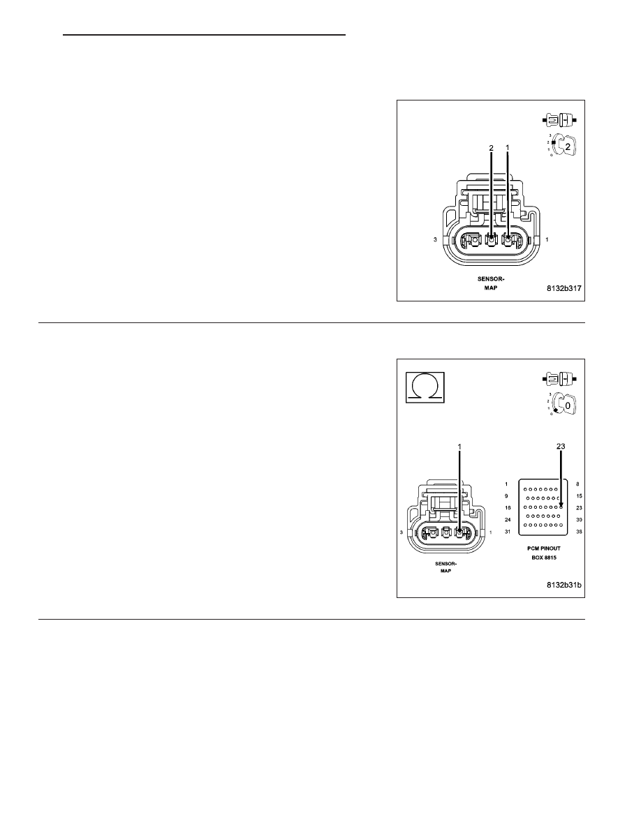
Measure the resistance of the (F856) 5-volt Supply circuit from the
MAP Sensor harness connector to the appropriate terminal of special
tool #8815.
Is the resistance below 5.0 ohms?
Yes
>> Go To 12
No
>> Repair the excessive resistance in the (F856) 5-volt Sup-
ply circuit.
Perform POWERTRAIN VERIFICATION TEST. (Refer to 9
- ENGINE - STANDARD PROCEDURE)
12.
(F856) 5-VOLT SUPPLY CIRCUIT SHORTED TO GROUND
Measure the resistance between ground and the (F856) 5-volt Supply
circuit in the MAP Sensor harness connector.
Is the resistance above 100k ohms?
Yes
>> Go To 13
No
>> Repair the short to ground in the (F856) 5-volt Supply cir-
cuit.
Perform POWERTRAIN VERIFICATION TEST. (Refer to 9
- ENGINE - STANDARD PROCEDURE)
9 - 54
ENGINE ELECTRICAL DIAGNOSTICS
ND
P0068-MANIFOLD PRESSURE/THROTTLE POSITION CORRELATION (CONTINUED)
13.
MAP SENSOR
Turn the ignition off.
Connect the C1 PCM harness connector.
Ignition on, engine not running.
With a scan tool, monitor the MAP Sensor voltage.
Connect a jumper wire between the (K1) MAP Signal circuit and the
(K900) Sensor ground circuit.
Does the scan tool display MAP voltage from approximately 4.9
volts to below 0.5 of a volt with the jumper wire installed?
Yes
>> Replace the MAP Sensor.
Perform POWERTRAIN VERIFICATION TEST. (Refer to 9
- ENGINE - STANDARD PROCEDURE)
No
>> Go To 14
NOTE: Remove the jumper wire before continuing.
14.
EXCESSIVE RESISTANCE IN THE (K1) MAP SIGNAL CIRCUIT
Turn the ignition off.
Disconnect the C2 PCM harness connector.
CAUTION: Do not probe the PCM harness connectors. Probing
the PCM harness connectors will damage the PCM terminals
resulting in poor terminal to pin connection. Install Miller Special
Tool #8815 to perform diagnosis.
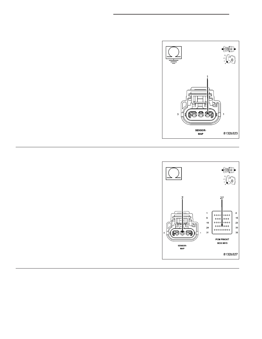
Measure the resistance of the (K1) MAP Signal circuit from the MAP
Sensor harness connector to the appropriate terminal of special tool
#8815.
Is the resistance below 5.0 ohms?
Yes
>> Go To 15
No
>> Repair the excessive resistance in the (K1) MAP Signal
circuit
Perform POWERTRAIN VERIFICATION TEST. (Refer to 9
- ENGINE - STANDARD PROCEDURE)
ND
ENGINE ELECTRICAL DIAGNOSTICS
9 - 55
P0068-MANIFOLD PRESSURE/THROTTLE POSITION CORRELATION (CONTINUED)
15.
(K1) MAP SIGNAL CIRCUIT SHORTED TO GROUND
Measure the resistance between ground and the (K1) MAP Signal cir-
cuit in the MAP Sensor harness connector.
Is the resistance below 100 ohms?
Yes
>> Repair the short to ground in the (K1) MAP Signal circuit.
Perform POWERTRAIN VERIFICATION TEST. (Refer to 9
- ENGINE - STANDARD PROCEDURE)
No
>>
Go To 16
16.
EXCESSIVE RESISTANCE IN THE (K900) SENSOR GROUND CIRCUIT
CAUTION: Do not probe the PCM harness connectors. Probing
the PCM harness connectors will damage the PCM terminals
resulting in poor terminal to pin connection. Install Miller Special
Tool #8815 to perform diagnosis.
Measure the resistance of the (K900) Sensor ground circuit from the
MAP Sensor harness connector to the appropriate terminal of special
tool #8815.
Is the resistance below 5.0 ohms?
Yes
>> Go To 17
No
>> Repair the excessive resistance in the (K900) Sensor
ground circuit.
Perform POWERTRAIN VERIFICATION TEST. (Refer to 9
- ENGINE - STANDARD PROCEDURE)
9 - 56
ENGINE ELECTRICAL DIAGNOSTICS
ND
P0068-MANIFOLD PRESSURE/THROTTLE POSITION CORRELATION (CONTINUED)
17.
PCM
NOTE: Before continuing, check the PCM harness connector terminals for corrosion, damage, or terminal
push out. Repair as necessary.
Using the schematics as a guide, inspect the wire harness and connectors. Pay particular attention to all Power and
Ground circuits.
Were there any problems found?
Yes
>> Repair as necessary.
Perform POWERTRAIN VERIFICATION TEST. (Refer to 9 - ENGINE - STANDARD PROCEDURE)
No
>> Replace and program the Powertrain Control Module per Service Information.
Perform POWERTRAIN VERIFICATION TEST. (Refer to 9 - ENGINE - STANDARD PROCEDURE)
ND
ENGINE ELECTRICAL DIAGNOSTICS
9 - 57
Нет комментариевНе стесняйтесь поделиться с нами вашим ценным мнением.
Текст