Dodge Dakota (ND). Manual — part 752
P0581-SPEED CONTROL SWITCH 1 CIRCUIT HIGH
9 - 546
ENGINE ELECTRICAL DIAGNOSTICS
ND
P0581-SPEED CONTROL SWITCH 1 CIRCUIT HIGH (CONTINUED)
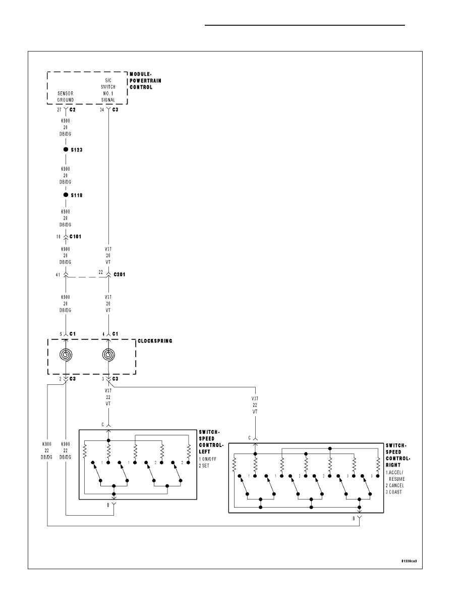
For the Engine circuit diagram (Refer to 9 - ENGINE - SCHEMATICS AND DIAGRAMS).
For a complete wiring diagram Refer to Section 8W.
•
When Monitored:
With the ignition key on. Battery voltage above 10 volts.
•
Set Condition:
The PCM detects an open or short to voltage in the Speed Control Switch Signal circuit. One Trip Fault. Three
good trips to turn off the MIL.
Possible Causes
(V37) S/C SWITCH NO.1 SIGNAL CIRCUIT SHORTED TO BATTERY VOLTAGE
(V37) S/C SWITCH NO.1 SIGNAL CIRCUIT OPEN BETWEEN PCM AND CLOCKSPRING
(K900) SENSOR GROUND CIRCUIT OPEN BETWEEN PCM AND CLOCKSPRING
(K900) SENSOR GROUND CIRCUIT OPEN BETWEEN CLOCKSPRING AND S/C SWITCH
(V37) S/C SWITCH NO.1 SIGNAL CIRCUIT OPEN BETWEEN CLOCKSPRING AND S/C SWITCH
CLOCKSPRING
SPEED CONTROL SWITCH
PCM
Always perform the Pre-Diagnostic Troubleshooting procedure before proceeding. (Refer to 9 - ENGINE -
DIAGNOSIS AND TESTING).
Diagnostic Test
1.
SPEED CONTROL SWITCH VOLTAGE HIGH
NOTE: Do not press any of the Speed Control Switch buttons.
Ignition on, engine not running.
With a scan tool, read the Speed Control voltage.
Is the Speed Control voltage above 4.8 volts?
Yes
>> Go To 2
No
>> Refer to the INTERMITTENT CONDITION Diagnostic Procedure.
Perform POWERTRAIN VERIFICATION TEST. (Refer to 9 - ENGINE - STANDARD PROCEDURE)
ND
ENGINE ELECTRICAL DIAGNOSTICS
9 - 547
P0581-SPEED CONTROL SWITCH 1 CIRCUIT HIGH (CONTINUED)
2.
SPEED CONTROL SWITCHES
Turn the ignition off.
Remove the Speed Control Switches from the steering wheel.
Measure the resistance across each Speed Control Switch.
Monitor the ohmmeter while pressing each function button on each switch.
Resume/Accel - 15.4 kohms
Cancel - 1.24 kohms
Coast - 2.94 kohms
On/Off - 0.47 kohms
Set - 5.49 kohms
Does the function on the Speed Control Switches have the correct resistance value?
Yes
>> Go To 3
No
>> Replace the Speed Control Switch that had the incorrect resistance value.
Perform POWERTRAIN VERIFICATION TEST. (Refer to 9 - ENGINE - STANDARD PROCEDURE)
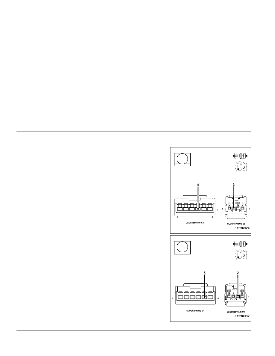
3.
CLOCKSPRING
Disconnect the C1 and C2 Clockspring harness connectors per Ser-
vice Information.
Measure the resistance of the (K900) Sensor ground circuit between
the upper and lower 6-way clockspring harness connectors.
Measure the resistance of the (V37) S/C Switch No.1 Signal circuit
between the upper and lower 6-way clockspring harness connectors.
Was the resistance above 5.0 ohms for either circuit?
Yes
>> Replace the clockspring.
Perform POWERTRAIN VERIFICATION TEST. (Refer to 9
- ENGINE - STANDARD PROCEDURE)
No
>> Go To 4
9 - 548
ENGINE ELECTRICAL DIAGNOSTICS
ND
P0581-SPEED CONTROL SWITCH 1 CIRCUIT HIGH (CONTINUED)
4.
(V37) S/C SWITH NO.1 SIGNAL CIRCUIT SHORTED TO BATTERY VOLTAGE
Connect the Clockspring harness connectors per Service Information.
Disconnect the C2 and C3 PCM harness connectors.
Ignition on, engine not running.
Measure the voltage on the (V37) S/C Switch No.1 Signal circuit in the
Speed Control harness connector.
Is the voltage above 5.3 volts?
Yes
>> Repair the short to battery voltage in the (V37) S/C Switch
No.1 Signal circuit.
Perform POWERTRAIN VERIFICATION TEST. (Refer to 9
- ENGINE - STANDARD PROCEDURE)
No
>> Go To 5
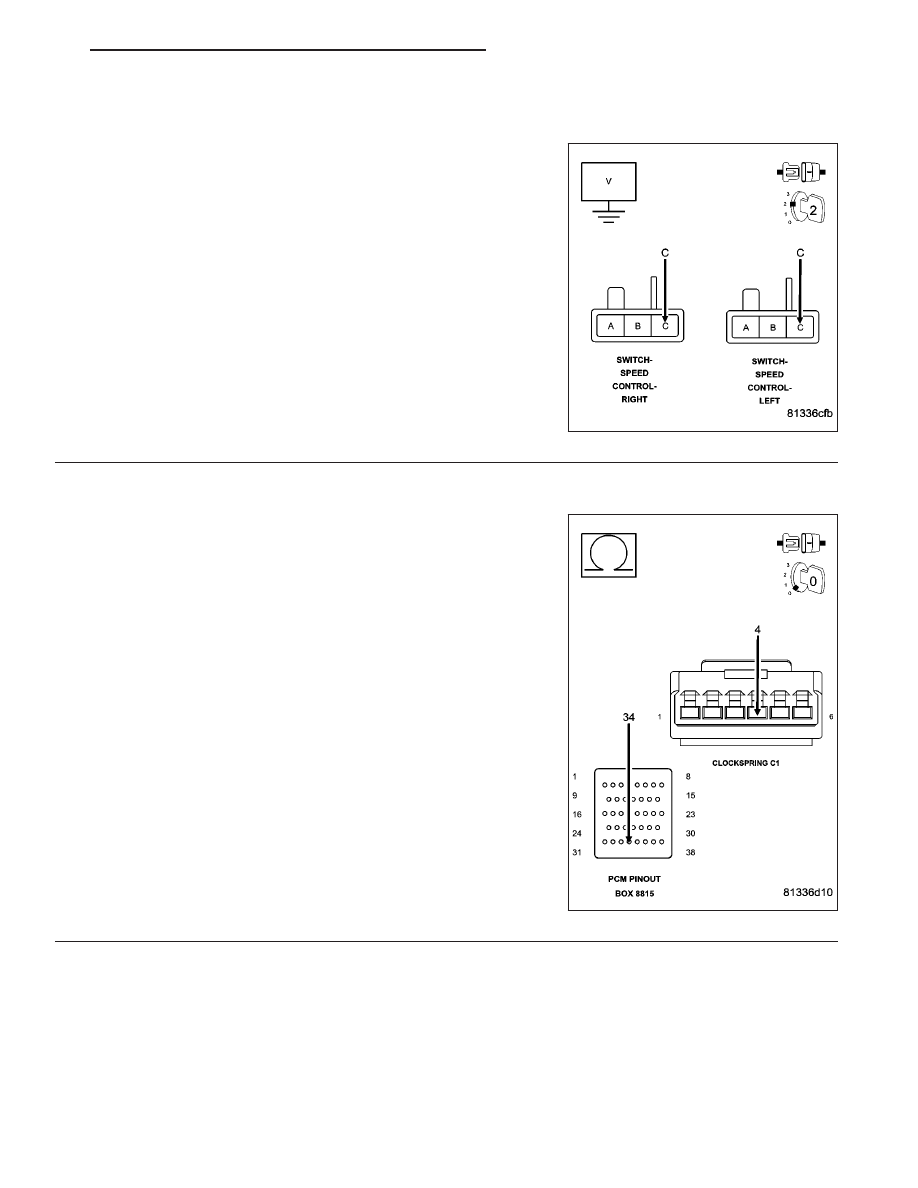
5.
(V37) S/C SWITCH NO.1 SIGNAL CIRCUIT OPEN BETWEEN PCM AND CLOCKSPRING
Turn the ignition off.
Disconnect the C1 and C2 Clockspring harness connectors per Ser-
vice Information.
CAUTION: Do not probe the PCM harness connectors. Probing
the PCM harness connectors will damage the PCM terminals
resulting in poor terminal to pin connection. Install Miller Special
Tool #8815 to perform diagnosis.
Measure the resistance of the (V37) S/C Switch No.1 Signal circuit
from the lower Clockspring harness connector to the appropriate ter-
minal of special tool #8815.
Is the resistance below 5.0 ohms?
Yes
>> Go To 6
No
>> Repair the open in the (V37) S/C Switch No.1 Signal cir-
cuit between the PCM and Clockspring.
Perform POWERTRAIN VERIFICATION TEST. (Refer to 9
- ENGINE - STANDARD PROCEDURE)
ND
ENGINE ELECTRICAL DIAGNOSTICS
9 - 549
Нет комментариевНе стесняйтесь поделиться с нами вашим ценным мнением.
Текст