Dodge Dakota (ND). Manual — part 751
P0580-SPEED CONTROL SWITCH 1 CIRCUIT LOW
9 - 542
ENGINE ELECTRICAL DIAGNOSTICS
ND
P0580-SPEED CONTROL SWITCH 1 CIRCUIT LOW (CONTINUED)
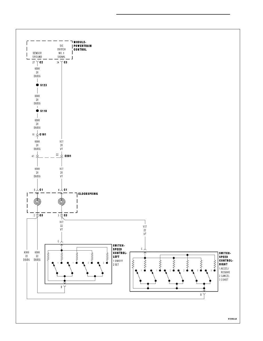
For the Engine circuit diagram (Refer to 9 - ENGINE - SCHEMATICS AND DIAGRAMS).
For a complete wiring diagram Refer to Section 8W.
•
When Monitored:
With the ignition key on. Battery voltage above 10 volts.
•
Set Condition:
When switch voltage is less than 0.43 of a volt for 2 minutes. One trip fault. Three good trips to turn off the
MIL.
Possible Causes
(V37) S/C SIGNAL NO.1 CIRCUIT SHORTED TO GROUND
(V37) S/C SIGNAL NO.1 CIRCUIT SHORTED TO THE (K900) SENSOR GROUND CIRCUIT
CLOCKSPRING
SPEED CONTROL ON/OFF SWITCH
SPEED CONTROL RESUME/ACCEL SWITCH
PCM
Always perform the Pre-Diagnostic Troubleshooting procedure before proceeding. (Refer to 9 - ENGINE -
DIAGNOSIS AND TESTING).
Diagnostic Test
1.
SPEED CONTROL SWITCH VOLTAGE LOW
NOTE: Do not press any of the Speed Control Switch buttons.
Ignition on, engine not running.
With a scan tool, read the Speed Control voltage.
Is the Speed Control voltage below 1.0 volt?
Yes
>> Go To 2
No
>> Refer to the INTERMITTENT CONDITION Diagnostic Procedure.
Perform POWERTRAIN VERIFICATION TEST. (Refer to 9 - ENGINE - STANDARD PROCEDURE)
2.
SPEED CONTROL ON/OFF SWITCH
Ignition on, engine not running.
With the scan tool, monitor the Speed Control Switch voltage.
Disconnect the Speed Control On/Off Switch harness connector per Service Information.
Did the voltage change to above 4.7 volts?
Yes
>> Replace the Speed Control On/Off Switch.
Perform POWERTRAIN VERIFICATION TEST. (Refer to 9 - ENGINE - STANDARD PROCEDURE)
No
>> Go To 3
ND
ENGINE ELECTRICAL DIAGNOSTICS
9 - 543
P0580-SPEED CONTROL SWITCH 1 CIRCUIT LOW (CONTINUED)
3.
SPEED CONTROL RESUME/ACCEL SWITCH
With the scan tool, monitor the Speed Control Switch voltage.
Disconnect the Speed Control Resume/Accel Switch harness connectors per Service Information.
Did the voltage change to above 4.7 volts?
Yes
>> Replace the Speed Control Resume/Accel Switch.
Perform POWERTRAIN VERIFICATION TEST. (Refer to 9 - ENGINE - STANDARD PROCEDURE)
No
>> Go To 4
4.
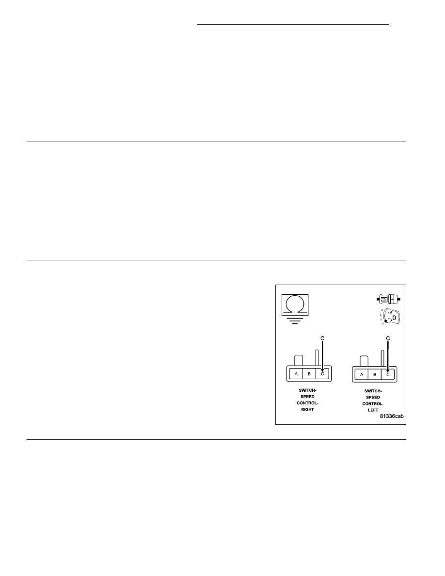
CLOCKSPRING
Turn the ignition off.
Disconnect the C1 Clockspring 6-way harness connector (instrument panel wiring side) per Service Information.
Ignition on, engine not running.
With the scan tool, read the S/C Switch voltage.
Did the S/C Switch volts change to 5.0 volts?
Yes
>> Replace the Clockspring.
Perform POWERTRAIN VERIFICATION TEST. (Refer to 9 - ENGINE - STANDARD PROCEDURE)
No
>> Go To 5
5.
(V37) S/C NO.1 SIGNAL CIRCUIT SHORTED TO GROUND
Turn the ignition off.
Connect the C1 Clockspring harness connector per Service Informa-
tion.
Disconnect the C2 and C3 PCM harness connectors.
Measure the resistance between ground and the (V37) S/C Signal cir-
cuit in one of the S/C Switch harness connectors.
Is the resistance below 100 ohms?
Yes
>> Repair the short to ground in the (V37) S/C Signal circuit.
Perform POWERTRAIN VERIFICATION TEST. (Refer to 9
- ENGINE - STANDARD PROCEDURE) )
No
>> Go To 6
9 - 544
ENGINE ELECTRICAL DIAGNOSTICS
ND
P0580-SPEED CONTROL SWITCH 1 CIRCUIT LOW (CONTINUED)
6.
(V37) S/C SIGNAL NO.1 CIRCUIT SHORTED TO THE (K900) SENSOR GROUND CIRCUIT
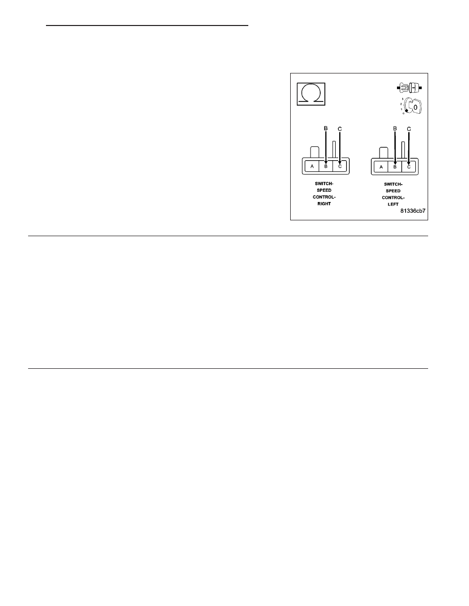
Measure the resistance between the (K900) Sensor ground circuit and
the (V37) S/C Signal No.1 circuit in the Speed Control Switch.
Is the resistance below 5.0 ohms?
Yes
>> Repair the short between the (V37) S/C Signal No.1 circuit
and the (K900) Sensor ground circuit.
Perform POWERTRAIN VERIFICATION TEST. (Refer to 9
- ENGINE - STANDARD PROCEDURE)
No
>> Go To 7
7.
PCM
NOTE: Before continuing, check the PCM harness connector terminals for corrosion, damage, or terminal
push out. Repair as necessary.
Using the schematics as a guide, inspect the wire harness and connectors. Pay particular attention to all Power and
Ground circuits.
Were there any problems found?
Yes
>> Repair as necessary.
Perform POWERTRAIN VERIFICATION TEST. (Refer to 9 - ENGINE - STANDARD PROCEDURE)
No
>> Replace and program the Powertrain Control Module per Service Information.
Perform POWERTRAIN VERIFICATION TEST. (Refer to 9 - ENGINE - STANDARD PROCEDURE)
ND
ENGINE ELECTRICAL DIAGNOSTICS
9 - 545
Нет комментариевНе стесняйтесь поделиться с нами вашим ценным мнением.
Текст