Dodge Dakota (ND). Manual — part 622
P0038-O2 SENSOR 1/2 HEATER CIRCUIT HIGH (CONTINUED)
For the Engine circuit diagram (Refer to 9 - ENGINE - SCHEMATICS AND DIAGRAMS).
For a complete wiring diagram Refer to Section 8W.
•
When Monitored:
Battery voltage above 10.6 volts, ASD is powered up, and O2 heater is off.
•
Set Condition:
Desired state does not equal Actual state. One Trip Fault. Three good trips to turn off the MIL.
Possible Causes
(K299) O2 1/2 HEATER CONTROL CIRCUIT OPEN
(Z42) O2 1/2 HEATER GROUND CIRCUIT OPEN
(K299) O2 SENSOR 1/2 HEATER CONTROL CIRCUIT SHORTED TO BATTERY VOLTAGE
O2 SENSOR
PCM
Always perform the Pre-Diagnostic Troubleshooting procedure before proceeding. (Refer to 9 - ENGINE -
DIAGNOSIS AND TESTING).
Diagnostic Test
1.
ACTIVE DTC
Ignition on, engine not running.
With a scan tool, read DTC’s.
Is the DTC active at this time?
Yes
>> Go To 2
No
>> Refer to the INTERMITTENT CONDITION Diagnostic Procedure.
Perform POWERTRAIN VERIFICATION TEST. (Refer to 9 - ENGINE - STANDARD PROCEDURE)
2.
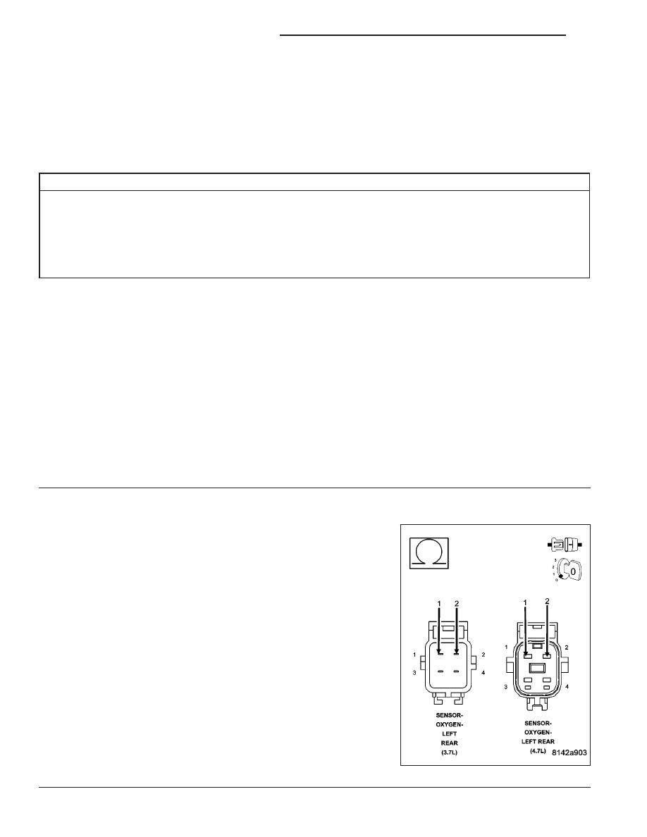
O2 HEATER ELEMENT
Turn the ignition off.
NOTE: Allow the O2 Sensor to cool down to room temperature.
Disconnect the 1/2 O2 Sensor harness connector.
Measure the resistance across the O2 Sensor Heater element,
between the Heater Control terminal and the Heater ground terminal at
the component.
NOTE: O2 Heater Element resistance values should be measured
at 70°F (21.1°C). The resistance value will vary with different tem-
perature values.
Is the O2 Sensor Heater Element resistance between 2.0 and
30.0 ohms?
Yes
>> Go To 3
No
>> Replace the O2 Sensor.
Perform POWERTRAIN VERIFICATION TEST. (Refer to 9
- ENGINE - STANDARD PROCEDURE)
9 - 26
ENGINE ELECTRICAL DIAGNOSTICS
ND
P0038-O2 SENSOR 1/2 HEATER CIRCUIT HIGH (CONTINUED)
3.
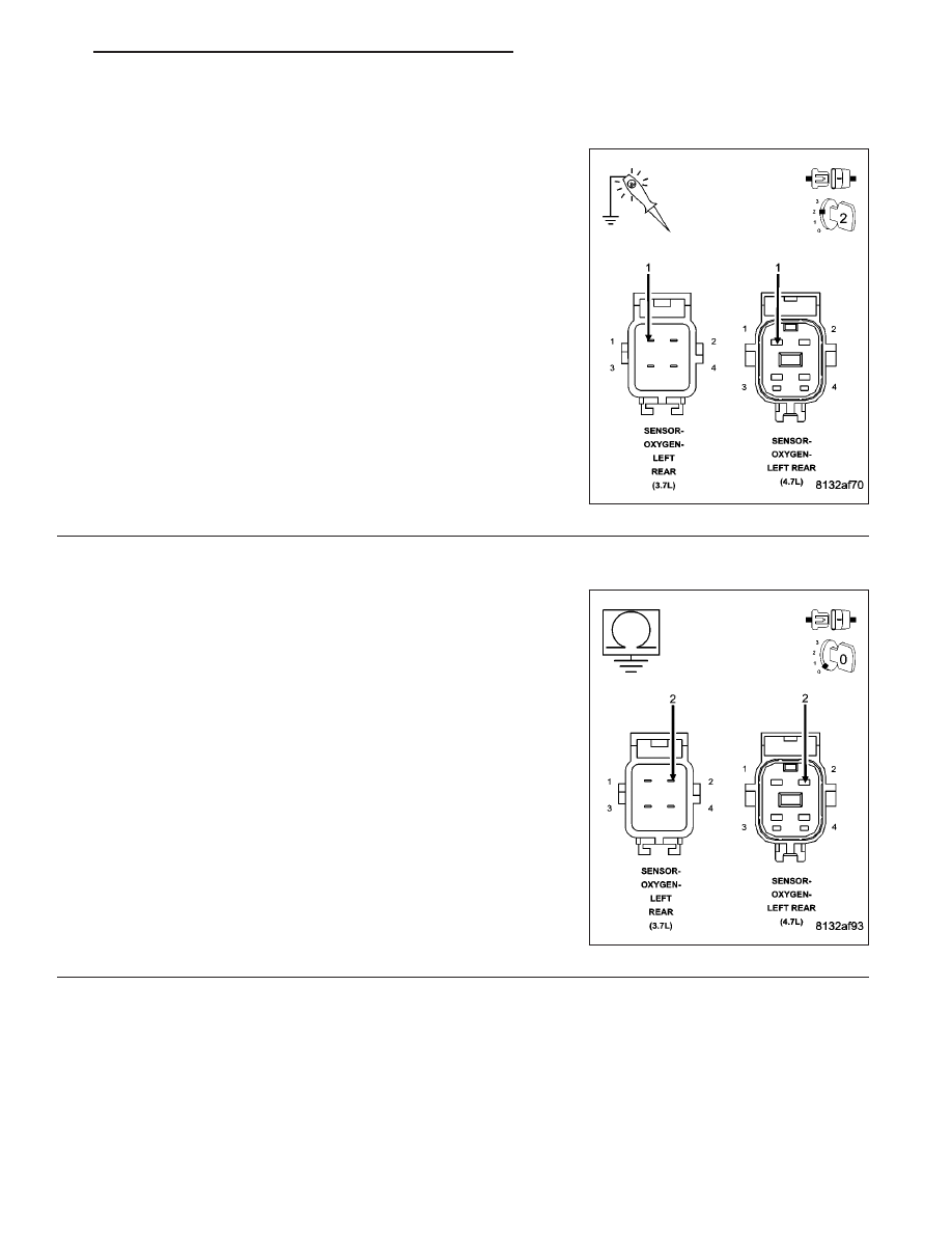
(K299) O2 1/2 HEATER CONTROL CIRCUIT
Ignition on, engine not running.
With a scan tool, actuate the O2 1/2 Heater Test with the O2 Sensor
harness connector still disconnected.
Using a 12-volt test light connected to ground, probe the (K299) O2
1/2 Heater Control circuit in the O2 Sensor harness connector.
Does the test light illuminate brightly and flash on and off dur-
ing the actuation?
Yes
>> Go To 4
No
>> Go To 5
4.
(Z42) O2 HEATER GROUND CIRCUIT OPEN
Turn the ignition off.
Measure the resistance between an engine ground and the (Z42) O2
1/2 Heater ground circuit in the O2 Sensor harness connector.
Is the resistance below 5.0 ohms?
Yes
>> Replace the O2 Sensor.
Perform POWERTRAIN VERIFICATION TEST. (Refer to 9
- ENGINE - STANDARD PROCEDURE)
No
>> Repair the open in the (Z42) O2 1/2 Heater ground circuit.
Perform POWERTRAIN VERIFICATION TEST. (Refer to 9
- ENGINE - STANDARD PROCEDURE)
ND
ENGINE ELECTRICAL DIAGNOSTICS
9 - 27
P0038-O2 SENSOR 1/2 HEATER CIRCUIT HIGH (CONTINUED)
5.
(K299) O2 1/2 HEATER CONTROL CIRCUIT SHORTED TO BATTERY VOLTAGE
Turn the ignition off.
Disconnect the C3 PCM harness connector.
Ignition on, engine not running.
Using a 12-volt test light connect to ground, probe the (K299) O2 1/2
Heater Control circuit in the O2 Sensor harness connector.
Does the test light illuminate brightly?
Yes
>> Repair the short to battery voltage in the (K299) O2 1/2
Heater Control circuit.
Perform POWERTRAIN VERIFICATION TEST. (Refer to 9
- ENGINE - STANDARD PROCEDURE)
No
>> Go To 6
6.
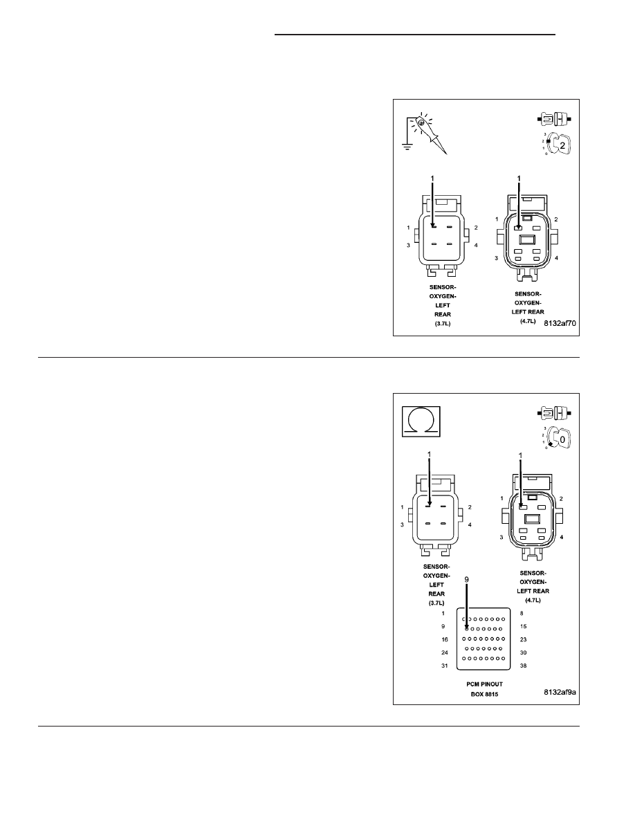
(K299) O2 1/2 HEATER CONTROL CIRCUIT OPEN
Turn the ignition off.
CAUTION: Do not probe the PCM harness connectors. Probing
the PCM hanrness connectors will damage the PCM terminals
resulting in poor terminal to pin connection. Install Miller Special
Tool #8815 to perform diagnosis.
Measure the resistance of the (K299) O2 1/2 Heater Control circuit
from the O2 Sensor harness connector to the appropriate terminal of
special tool #8815.
Is the resistance below 5.0 ohms?
Yes
>> Go To 7
No
>> Repair the open in the (K299) O2 1/2 Heater Control cir-
cuit.
Perform POWERTRAIN VERIFICATION TEST. (Refer to 9
- ENGINE - STANDARD PROCEDURE)
9 - 28
ENGINE ELECTRICAL DIAGNOSTICS
ND
P0038-O2 SENSOR 1/2 HEATER CIRCUIT HIGH (CONTINUED)
7.
PCM
NOTE: Before continuing, check the PCM harness connector terminals for corrosion, damage, or terminal
push out. Repair as necessary.
Using the schematics as a guide, inspect the wire harness and connectors. Pay particular attention to all Power and
Ground circuits.
Were there any problems found?
Yes
>> Repair as necessary.
Perform POWERTRAIN VERIFICATION TEST. (Refer to 9 - ENGINE - STANDARD PROCEDURE)
No
>> Replace and program the Powertrain Control Module per Service Information.
Perform POWERTRAIN VERIFICATION TEST. (Refer to 9 - ENGINE - STANDARD PROCEDURE)
ND
ENGINE ELECTRICAL DIAGNOSTICS
9 - 29
Нет комментариевНе стесняйтесь поделиться с нами вашим ценным мнением.
Текст