Dodge Dakota (ND). Manual — part 1141
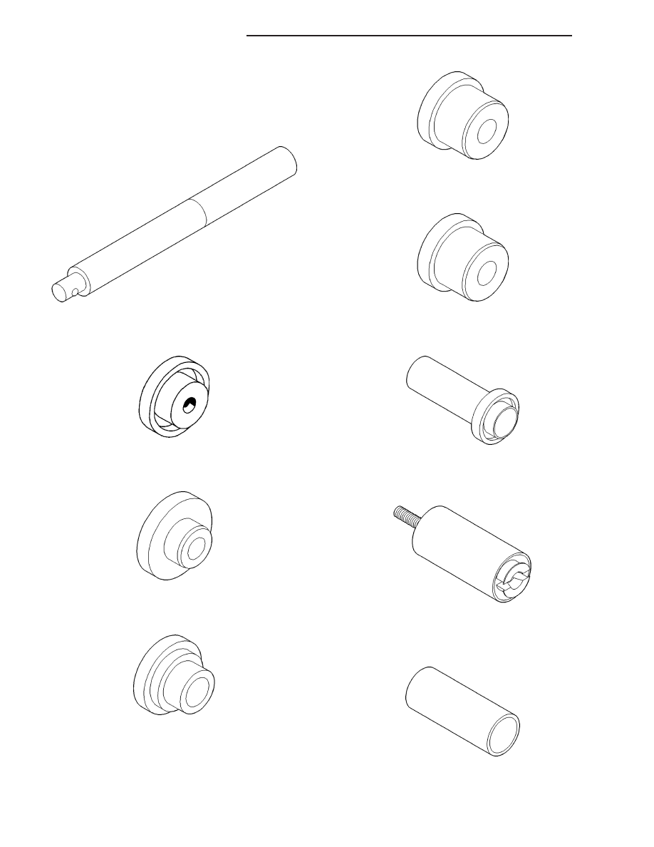
SPECIAL TOOLS
TRANSFER CASE - NV244
Handle, Universal - C-4171
Remover, Bearing - C-4210
Installer, Bearing - 5064
Installer, Bearing - 8128
Installer, Bearing - 5066
Installer, Bearing - 5066
Installer, Seal - 6952-A
Remover, Bearing - L-4454
Cup - 8148
21 - 956
TRANSFER CASE - NV244
ND
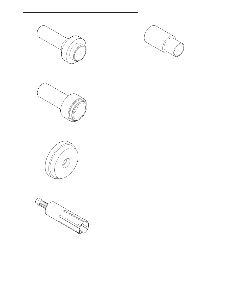
Installer, Seal - 7884
Installer, Pump Housing Seal - 7888
Installer, Bearing - 8033-A
Remover, Bushing - 8158
Installer, Bushing - 8157
ND
TRANSFER CASE - NV244
21 - 957
FLUID
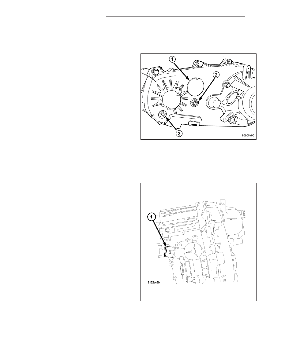
STANDARD PROCEDURE - FLUID DRAIN AND REFILL
The fill (2) and drain (3) plugs are both in the rear
case.
1. Raise vehicle.
2. Position drain pan under transfer case.
3. Remove drain and fill plugs and drain lubricant
completely.
4. Install drain plug. Tighten plug to 20-34 N·m (15-25
ft. lbs.).
5. Remove drain pan.
6. Fill transfer case to bottom edge of fill plug opening
with Mopar
T
ATF +4, Automatic Transmission fluid.
7. Install and tighten fill plug to 20-34 N·m (15-25 ft.
lbs.).
8. Lower vehicle.
SENSOR-MODE
DESCRIPTION
The transfer case mode sensor (1) provides the Front
Control Module (FCM) feedback about the position of
the transfer case. The sensor consists of a linear ana-
log position sensor that converts the motor output
shaft position into a DC signal. The FCM must supply
5VDC (+/- 0.5v) to the sensor whenever the FCM is
not in sleep mode and monitor the shift motor position.
The sensor position is monitored when the ignition is
in the RUN position and for 10 seconds after the igni-
tion is shifted to the OFF position. The sensor is
mechanically linked to the shaft of the cam which
allows the transfer case to shift. The mode sensor will
draw less than 20 mA of current during operation.
OPERATION
During normal vehicle operation, the Front Control Module (FCM) monitors the mode sensor outputs at least every
2 milliseconds when the shift motor is stationary or active.
Refer to SECTOR ANGLES vs. TRANSFER CASE POSITION for the relative angles of the transfer case shift sector
versus the interpreted transfer case gear operating mode.
21 - 958
TRANSFER CASE - NV244
ND
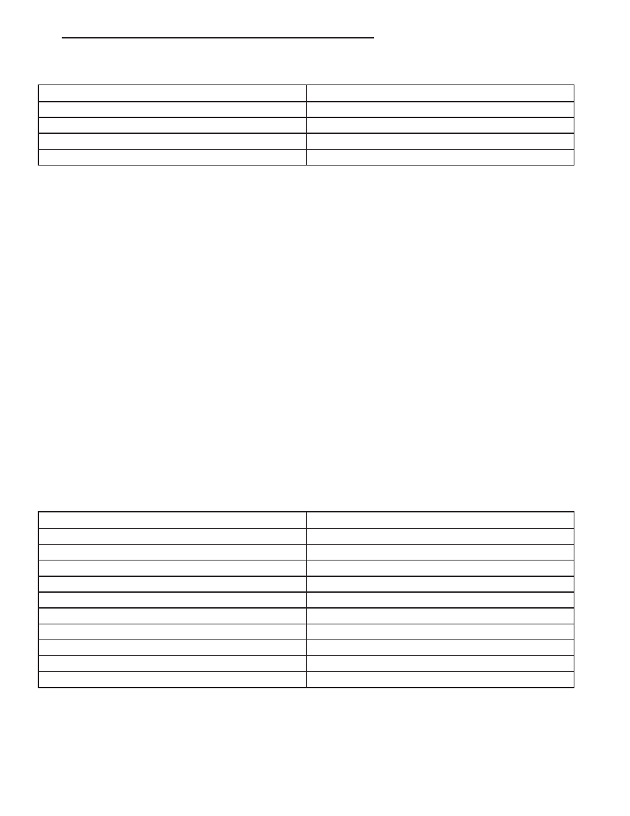
SECTOR ANGLES vs. TRANSFER CASE POSITION
Shaft Angle (Degrees)
Transfer Case Position
+20
4LO
0
N
-20
AWD
-40
4LOCK
NOTE: All the parameter voltages referred to in the following information are calibrated items in the con-
troller software and are subject to change.
NOTE: For a further explanation of Phase 1 through 3 shifting, (Refer to 8 - ELECTRICAL/ELECTRONIC
CONTROL MODULES/TRANSFER CASE CONTROL MODULE - OPERATION).
The following information describes the different mode sensor positions:
•
4LO TARGET REGION - The position shall be considered 4LO if the voltage is greater than or equal to
encoder_4LO_min Volts and it is also less than or equal to encoder_4LO_max Volts.
•
4LO SHIFT LIMIT - During Phase 2 and Phase 3 shifting, shifts may become unidirectional when a voltage is
less than or equal to encoder_4LO_min Volts has been reached.
•
4LOCK TARGET REGION - The position shall be considered 4LOCK if the voltage is greater than or equal to
encoder_4LOCK_min Volts and it is also less than or equal to encoder_4LOCK_max Volts.
•
NEUTRAL TARGET REGION - The position shall be considered NEUTRAL if the voltage is greater than or
equal to encoder_Neutral_min Volts and it is also less than or equal to encoder_Neutral_max Volts.
•
AWD TARGET REGION - The position shall be considered AWD if the voltage is greater than or equal to
encoder_AWD_min Volts and it is also less than or equal to encoder_AWD_max Volts.
•
AWD SHIFT LIMIT - During Phase 2 and Phase 3 shifting, shifts may become unidirectional when a voltage is
greater than or equal to encoder_AWD_min Volts has been reached.
The mode sensor position will be considered invalid by the FCM if the voltage is greater than or equal to encoder-
_High_Range_Limit Volts or if it is less than or equal to encoder_Low_Range_Limit Volts.
Refer to MODE SENSOR VOLTAGES - NV244 table for the mode sensor voltages.
MODE SENSOR VOLTAGES - NV244
Parameter Name
Voltage
encoder_4LOCK_Min
4.26
encoder_4LOCK_Max
4.36
encoder_AWD_Min
3.36
encoder_AWD_Max
3.44
encoder_Neutral_Min
2.45
encoder_Neutral_Max
2.54
encoder_4LO _Min
1.48
encoder_4LO _Max
1.57
encoder_High_Range_Limit
4.51
encoder_Low_Range _Limit
0.50
ND
TRANSFER CASE - NV244
21 - 959
Нет комментариевНе стесняйтесь поделиться с нами вашим ценным мнением.
Текст