Dodge Dakota (ND). Manual — part 1142
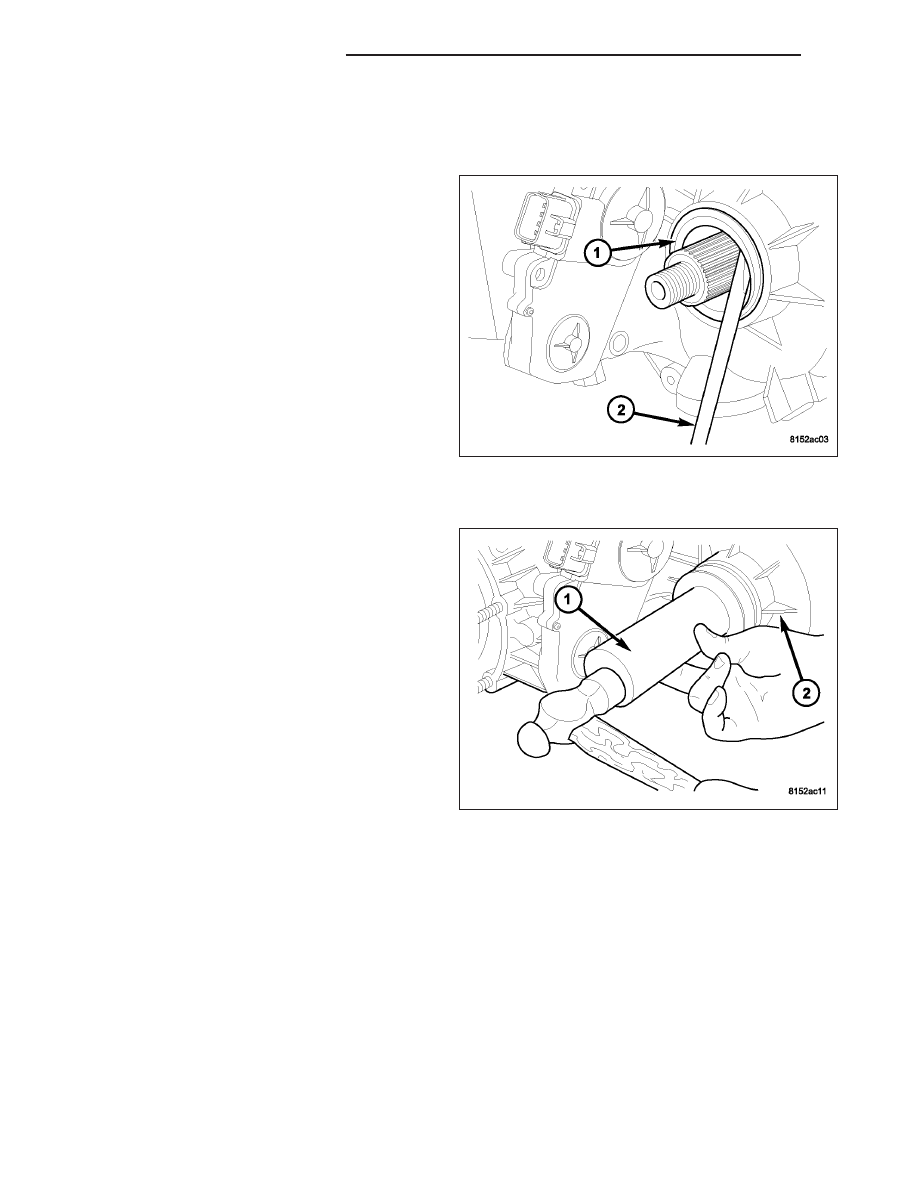
SEAL-FRONT OUTPUT SHAFT
REMOVAL
1. Raise vehicle.
2. Remove front propeller shaft. (Refer to 3 - DIFFER-
ENTIAL & DRIVELINE/PROPELLER SHAFT/PRO-
PELLER SHAFT - REMOVAL)
3. Remove front output shaft companion flange.
4. Remove seal (1) from front case with suitable pry
tool.
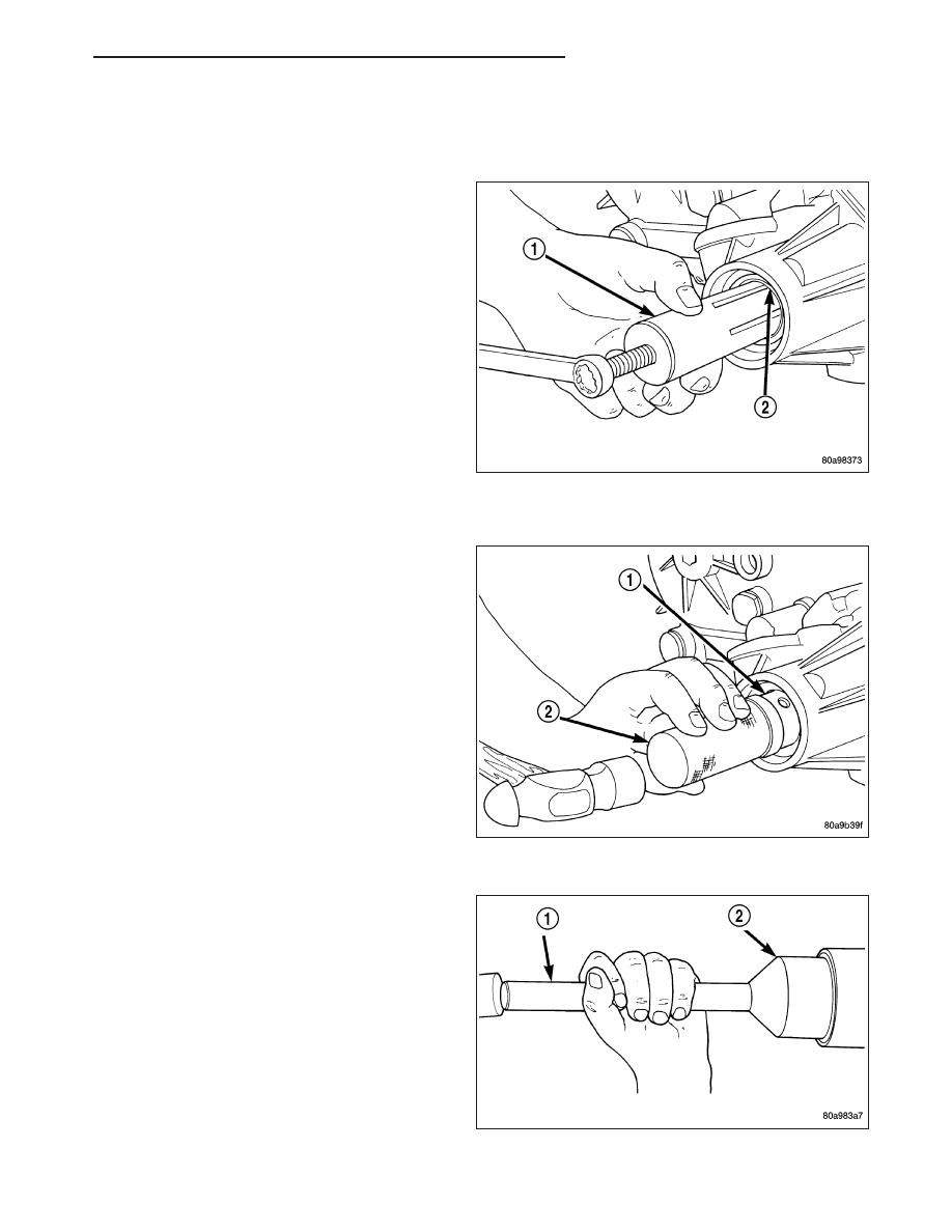
INSTALLATION
1. Install new front output seal in front case (2) with
Installer Tool 8143-A (1) as follows:
a. Place new seal on tool. Garter spring on seal
goes toward interior of case.
b. Start seal in bore with light taps from hammer.
Once seal is started, continue tapping seal into
bore until installer tool seats against case.
2. Install the front output shaft companion flange.
Tighten the flange nut to 122-176 N·m (90-130
ft.lbs.).
3. Install the front propeller shaft. (Refer to 3 - DIF-
FERENTIAL & DRIVELINE/PROPELLER SHAFT/
PROPELLER SHAFT - INSTALLATION)
21 - 960
TRANSFER CASE - NV244
ND
BUSHING/SEAL-REAR RETAINER
REMOVAL
1. Raise vehicle.
2. Remove rear propeller shaft. (Refer to 3 - DIFFER-
ENTIAL & DRIVELINE/PROPELLER SHAFT/PRO-
PELLER SHAFT - REMOVAL)
3. Using a suitable pry tool or slide-hammer mounted
screw, remove the rear retainer seal.
4. Using Remover 8158 (1), remove the bushing from
rear retainer.
INSTALLATION
1. Clean fluid residue from sealing surface and
inspect for defects.
2. Position replacement bushing in rear retainer with
fluid port in bushing aligned with slot in retainer.
3. Using Installer 8157 (2), drive bushing (1) into
retainer until installer seats against case.
4. Using Installer D-163 (2), install seal in rear
retainer.
5. Install the rear propeller shaft. (Refer to 3 - DIF-
FERENTIAL & DRIVELINE/PROPELLER SHAFT/
PROPELLER SHAFT - INSTALLATION)
6. Verify proper fluid level.
7. Lower vehicle.
ND
TRANSFER CASE - NV244
21 - 961
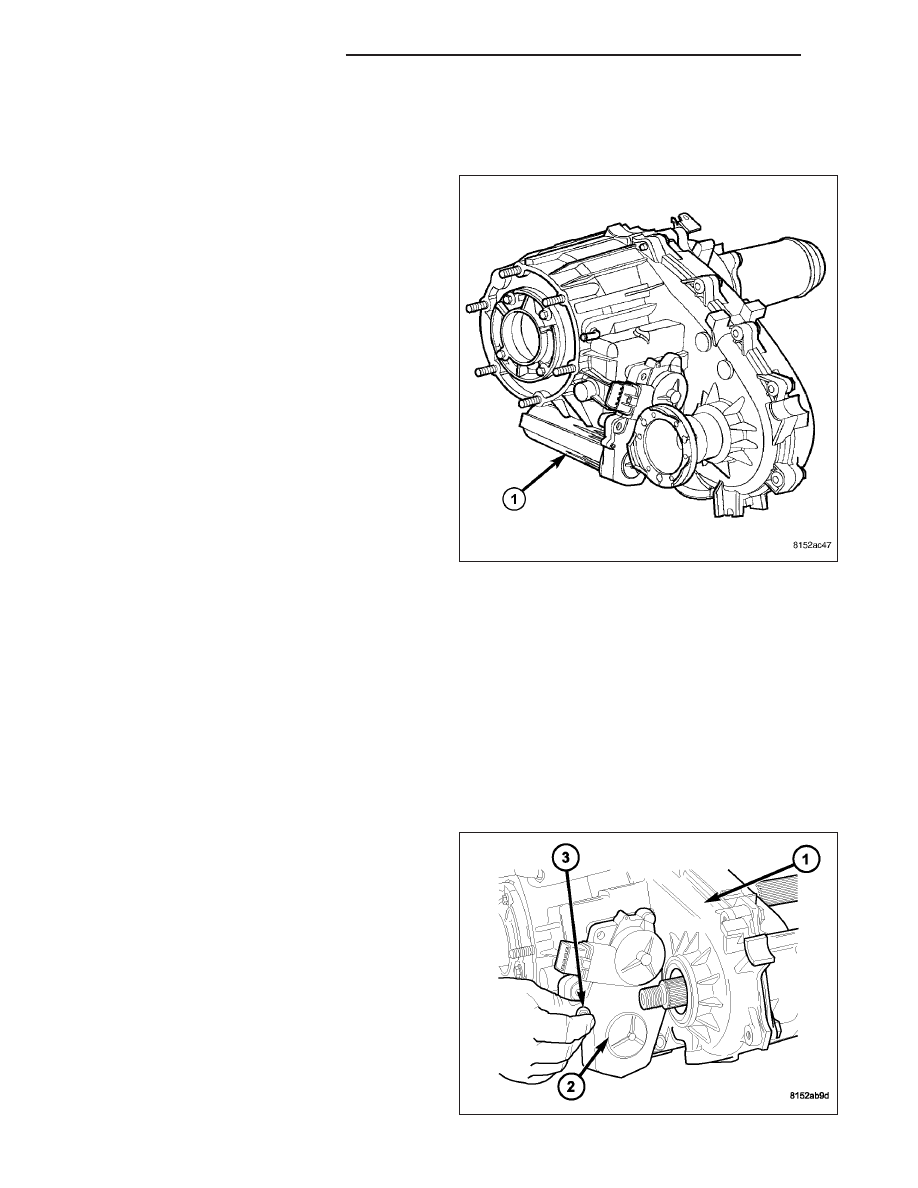
ASSEMBLY-SHIFT MOTOR/MODE SENSOR
DESCRIPTION
The shift motor (1) is an electromechanical device
consisting of a DC permanent magnet motor, gear
train, and an analog position sensor. The shift motors’
overall function is to move and lock a gear that moves
the mode and range forks found in the transfer case.
This allows the transfer case to be shifted electrically
to multiple operating positions (4LOCK, AWD, N (neu-
tral), and 4LO). The operating current of the shift
motor under stall conditions is 30 amps maximum at
72° F with 13.5 volts, at the motor leads.
OPERATION
Shifting in the transfer case occurs when a Pulse Width Modulated (PWM) voltage is supplied to the shift motor by
the Front Control Module (FCM). A linear analog position sensor located inside the shift motor, provides the FCM
with the motors’ angular, rotational position. With this information, the FCM continuously knows the motors’ position,
and therefore allows it to accurately control the motors’ operation, including voltage polarity which is used to control
motor direction.
REMOVAL
NOTE: New shift motor assemblies are shipped in the 2WD/AWD position. If a new shift motor assembly
must be installed, it will be necessary to shift the transfer case to the 2WD/AWD position prior to motor
installation.
1. Raise the vehicle on a suitable hoist.
2. Disengage the wiring connector from the shift
motor and mode sensor assembly.
3. Remove the bolts (3) holding the shift motor and
mode sensor assembly (2) onto the transfer case
(1).
4. Separate the shift motor and mode sensor assem-
bly (2) from the transfer case (1).
21 - 962
TRANSFER CASE - NV244
ND
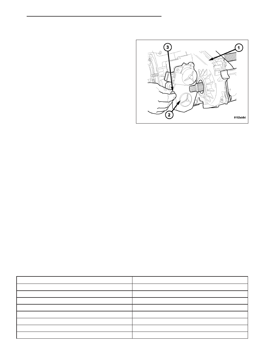
INSTALLATION
1. Verify that the shift motor o-ring is clean and prop-
erly positioned inside the machined o-ring groove
of the shift motor.
2. Add high temperature grease between the actuator
and the transfer case mating surface for sealing
purposes.
NOTE: Verify that the shift motor position and sec-
tor shaft orientation are aligned. It may be neces-
sary to manually shift the transfer case if the shift
motor and sector shaft are not aligned.
3. Position the shift motor and mode sensor assembly
(2) onto the transfer case (1).
4. Install the bolts (3) to hold the assembly (2) onto
the transfer case (1). Tighten the bolts to 16-24
N·m (12-18 ft.lbs.).
CAUTION: If the original shift motor and mode sensor assembly bolts are reused, be sure to use Mopar
T
Lock & Seal or Loctite™ 242 to replenish the lock patch material originally found on the bolts
5. Engage the wiring connector to the shift motor and mode sensor assembly.
6. Refill the transfer case as necessary.
7. Lower vehicle and verify transfer case operation.
SWITCH-TRANSFER CASE SELECTOR
DESCRIPTION
The selector switch assembly is mounted in the right side of the vehicle’s Instrument Panel (IP) and consists of a
rotary knob connected to a resistive network for the mode and range shift selections. Also located in this assembly
is a recessed, normally open momentary switch for making shifts into and out of transfer case NEUTRAL. A pen, or
similar instrument, is used to make a NEUTRAL shift selection, thus reducing the likelihood of an inadvertent shift
request.
OPERATION
As the position of the selector switch varies, the resistance between the Mode Sensor supply voltage pin and the
Mode Sensor output will vary. Hardware, software, and calibrations within the Front Control Module (FCM) are pro-
vided that interpret the selector switch resistance as given in the table below: SELECTOR SWITCH INTERPRETA-
TION
SELECTOR SWITCH INTERPRETATION
Required Interpretation
Resistance Range (ohms)
Shorted
<150
AWD+NEUTRAL
176-200
4LOCK+NEUTRAL
190-216
4LO+NEUTRAL
199-226
AWD (Default)
1159-1287
4LOCK
2259-2503
4LO
4820-5334
Open/Diagnostic
>19K
ND
TRANSFER CASE - NV244
21 - 963
Нет комментариевНе стесняйтесь поделиться с нами вашим ценным мнением.
Текст