Dodge Dakota (ND). Manual — part 258
B2100-IGNITION RUN/START INPUT CIRCUIT PERFORMANCE
8I - 2
IGNITION SYSTEM - ELECTRICAL DIAGNOSTICS
ND

B2100-IGNITION RUN/START INPUT CIRCUIT PERFORMANCE (CONTINUED)
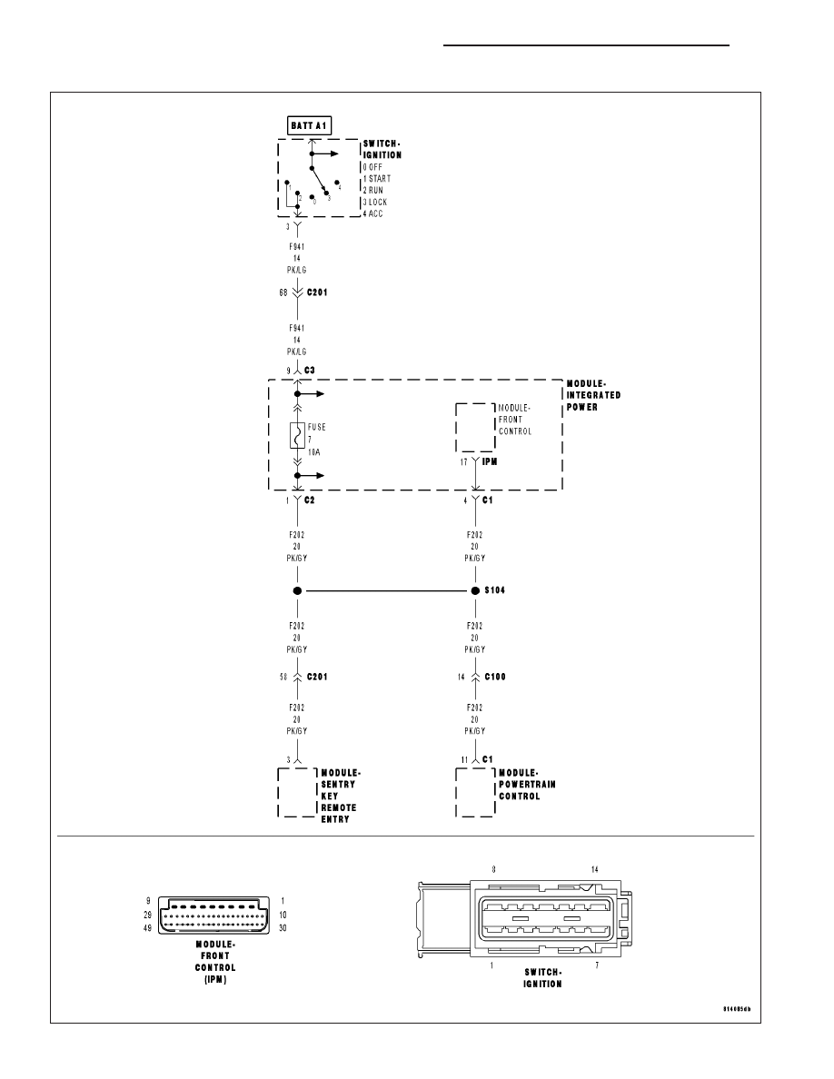
For a complete wiring diagram Refer to Section 8W.
•
When Monitored:
With the ignition on.
•
Set Condition:
The Front Control Module will set this DTC if the CAN bus message and the hardwired ignition switch circuit
do not match the position of the ignition switch.
Possible Causes
INTERGRATED POWER MODULE FUSE
(F941) FUSED IGNITION SWITCH OUTPUT CIRCUIT OPEN
INTERGRATED POWER MODULE
FRONT CONTROL MODULE
Diagnostic Test
1.
CHECK FOR ACTIVE DTC
With the scan tool, read the active DTC’s.
Cycle the ignition switch from off to on, leaving the ignition on for a minimum of 90 seconds.
With the scan tool, read the active DTC’s.
Does the scan tool display this DTC as active?
Yes
>> Go To 2
No
>> If the DTC is stored, check for an intermittent condition. Visually inspect the related wiring harness con-
nectors. Look for broken, bent, pushed out, or corroded terminals.
2.
INSPECT ALL IPM FUSES
Turn the ignition off.
Inspect the IPM fuses.
Are any fuses open?
Yes
>> Replace fuse and retest.
Perform BODY VERIFICATION TEST - VER 1. (Refer to BODY VERIFICATION TEST - VER 1).
No
>> Go To 3
ND
IGNITION SYSTEM - ELECTRICAL DIAGNOSTICS
8I - 3
B2100-IGNITION RUN/START INPUT CIRCUIT PERFORMANCE (CONTINUED)
3.
(F941) IGNITION SWITCH OUTPUT CIRCUIT OPEN
Turn the ignition off.
Disconnect the Integrated Power Module C3 harness connector.
Turn the ignition on.
Measure the voltage of the (F941) Ignition Switch Output circuit.
Is the voltage above 10.0 volts?
Yes
>> Go To 4
No
>> Repair the (F941) Ignition Switch Output circuit for an
open. Refer to the wiring diagrams located in 8W.
Perform BODY VERIFICATION TEST - VER 1. (Refer to
BODY VERIFICATION TEST - VER 1).
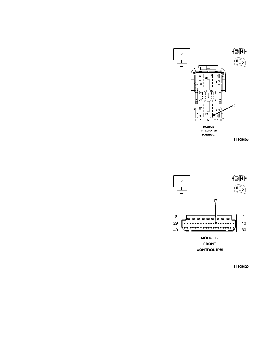
4.
(F202) FUSED IGNITION SWITCH OUTPUT CIRCUIT OPEN
Turn the ignition off.
Reconnect the Integrated Power Module C3 harness connector.
Remove the FCM from the IPM.
Turn the ignition on.
Measure the voltage of the (F202) Fused Ignition Switch Output circuit.
Is the voltage above 10.0 volts?
Yes
>> Inspect the wiring and connectors for damage or shorted
circuits. If ok, replace and program the Front Control Mod-
ule in accordance with the service information.
Perform BODY VERIFICATION TEST - VER 1. (Refer to
BODY VERIFICATION TEST - VER 1).
No
>> Replace the Integrated Power Module in accordance with
the service information.
Perform BODY VERIFICATION TEST - VER 1. (Refer to
BODY VERIFICATION TEST - VER 1).
8I - 4
IGNITION SYSTEM - ELECTRICAL DIAGNOSTICS
ND
IGNITION SYSTEM - SERVICE INFORMATION
TABLE OF CONTENTS
page
page
IGNITION SYSTEM - SERVICE INFORMATION
. . . . . . . . . . . . . . . . . . . . . . . . . . 5
SPECIFICATIONS - TORQUE - IGNITION
ENGINE FIRING ORDER - 3.7L V-6
ENGINE FIRING ORDER – 4.7L V-8
. . . . . . . . . . . . . . . . . . . . . . . . 7
IGNITION COIL RESISTANCE - 3.7L V-6
IGNITION COIL RESISTANCE - 4.7L V-8
. . . . . . . . . . . . . . . . . . . . . . 8
RELAY-AUTO SHUT DOWN
. . . . . . . . . . . . . . . . . . . . . . . . . 8
. . . . . . . . . . . . . . . 8
. . . . . . . . . . . . . . . . . . . . . . . . . . . . . . 8
. . . . . . . . . . . . . . . . . . . . . . . . . . 8
SENSOR-CAMSHAFT POSITION
. . . . . . . . . . . . . . . . . . . . . . . . . . 9
. . . . . . . . . . . . . . . . . . . . . . . . . . . . 9
. . . . . . . . . . . . . . . . . . . . . . . . . . . . . 10
. . . . . . . . . . . . . . . . . . . . . . . . . 11
COIL-IGNITION
. . . . . . . . . . . . . . . . . . . . . . . . . 12
. . . . . . . . . . . . . . . . . . . . . . . . . . . 13
. . . . . . . . . . . . . . . . . . . . . . . . . . . . . 14
. . . . . . . . . . . . . . . . . . . . . . . . . 16
SENSOR-KNOCK
. . . . . . . . . . . . . . . . . . . . . . . . . 17
. . . . . . . . . . . . . . . . . . . . . . . . . . . 17
. . . . . . . . . . . . . . . . . . . . . . . . . . . . . 18
. . . . . . . . . . . . . . . . . . . . . . . . . 19
SPARK PLUG
. . . . . . . . . . . . . . . . . . . . . . . . . 19
. . . . . . . . . . . . . . . . . . . . . . . . . . . . . 19
. . . . . . . . . . . . . . . . . . . . . . . . . 20
SWITCH-IGNITION
. . . . . . . . . . . . . . . . . . . . . . . . . 21
. . . . . . . . . . . . . . . . . . . . . . . . . . . 21
. . . . . . . . . . . . . . . . . . . . 21
. . . . . . . . . . . . . . . . . . . . . . . . . . . . . 22
. . . . . . . . . . . . . . . . . . . . . . . . . 24
SWITCH-KEY-IN IGNITION
. . . . . . . . . . . . . . . . . . . . . . . . . 25
CYLINDER . . . . . . . . . . . . . . . . . . . . . . . . . . . 25
CYLINDER-KEY/LOCK
. . . . . . . . . . . . . . . . . . . . . . . . . . . . . 26
. . . . . . . . . . . . . . . . . . . . . . . . . 27
IGNITION SYSTEM - SERVICE INFORMATION
DESCRIPTION
The ignition system is controlled by the Powertrain Control Module (PCM) on all engines.
3.7L V-6 ENGINE
The 3.7L V-6 engine uses a separate ignition coil for each cylinder. The one-piece coil bolts directly to the cylinder
head. Rubber boots seal the secondary terminal ends of the coils to the top of all 6 spark plugs. A separate elec-
trical connector is used for each coil.
Because of coil design, spark plug cables (secondary cables) are not used. A distributor is not used with the 3.7L
engine.
Two knock sensors (one for each cylinder bank) are used to help control spark knock.
The Auto Shutdown (ASD) relay provides battery voltage to each ignition coil.
The ignition system consists of:
•
6 Spark Plugs
•
6 Separate Ignition Coils
•
2 Knock Sensors
•
Powertrain Control Module (PCM)
•
Also to be considered part of the ignition system are certain inputs from the Crankshaft Position, Camshaft
Position, Throttle Position, 2 knock and MAP Sensors
ND
IGNITION SYSTEM - SERVICE INFORMATION
8I - 5
Нет комментариевНе стесняйтесь поделиться с нами вашим ценным мнением.
Текст