Dodge Dakota (ND). Manual — part 259
4.7L V-8 ENGINE
The 4.7L V-8 engine uses a separate ignition coil for each cylinder. The one-piece coil bolts directly to the cylinder
head. Rubber boots seal the secondary terminal ends of the coils to the top of all 8 spark plugs. A separate elec-
trical connector is used for each coil.
Because of coil design, spark plug cables (secondary cables) are not used. A distributor is not used with the 4.7L
engine.
Two knock sensors (one for each cylinder bank) are used to help control spark knock.
The Auto Shutdown (ASD) relay provides battery voltage to each ignition coil.
The ignition system consists of:
•
8 Spark Plugs
•
8 Separate Ignition Coils
•
2 Knock Sensors
•
Powertrain Control Module (PCM)
•
Also to be considered part of the ignition system are certain inputs from the Crankshaft Position, Camshaft
Position, Throttle Position, 2 knock and MAP Sensors
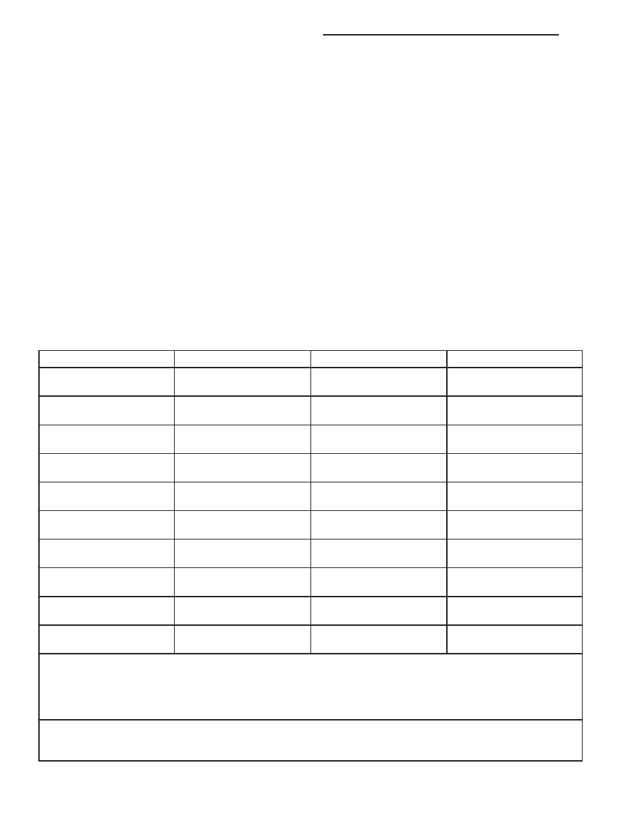
SPECIFICATIONS
SPECIFICATIONS - TORQUE - IGNITION
DESCRIPTION
N·m
Ft. Lbs.
In. Lbs.
Camshaft Position Sensor
- 3.7L V-6 Engine
12
-
106
Camshaft Position Sensor
- 4.7L V-8 Engine
12
-
106
Crankshaft Position
Sensor - 3.7L V-6 Engine
28
21
205
Crankshaft Position
Sensor - 4.7L V-8 Engine
28
21
205
Ignition Coil Mounting -
3.7L V-6 Engine
8
-
70
Ignition Coil Mounting -
4.7L V-8 Engine
8
-
70
* Knock Sensor - 3.7L V-6
Engine
20
15
176
* Knock Sensor - 4.7L V-8
Engine
20
15
176
Spark Plugs - 3.7L V-6
Engine
27
20
-
Spark Plugs - 4.7L V-8
Engine
27
20
-
* Do not apply any
sealant, thread-locker or
adhesive to bolts. Poor
sensor performance may
result.
** Torque critical tapered
design. Do not exceed 15
ft. lbs.
8I - 6
IGNITION SYSTEM - SERVICE INFORMATION
ND

ENGINE FIRING ORDER - 3.7L V-6
1 - 6 - 5 - 4 - 3 - 2
ENGINE FIRING ORDER – 4.7L V-8
SPARK PLUG CABLE RESISTANCE
MINIMUM
MAXIMUM
250 Ohms Per Inch
1000 Ohms Per Inch
3000 Ohms Per Foot
12,000 Ohms Per Foot
SPARK PLUGS
ENGINE
PLUG TYPE
ELECTRODE GAP
3.7L V-6
ZFR6F - 11G (NGK)
1.1 (0.042 in.)
4.7L V-8
RC12MCC4
1.01 mm (.040 in.)
IGNITION COIL RESISTANCE - 3.7L V-6
PRIMARY RESISTANCE
21-27°C (70-80°F)
SECONDARY
RESISTANCE 21-27°C
(70-80°F)
0.6 - 0.9 Ohms
6,000 - 9,000 Ohms
ND
IGNITION SYSTEM - SERVICE INFORMATION
8I - 7

IGNITION COIL RESISTANCE - 4.7L V-8
PRIMARY
RESISTANCE 21-27°C
(70-80°F)
SECONDARY
RESISTANCE 21-27°C
(70-80°F)
0.6 - 0.9 Ohms
6,000 - 9,000 Ohms
IGNITION TIMING
Ignition timing is not adjustable on any engine.
RELAY-AUTO SHUT DOWN
DESCRIPTION - PCM OUTPUT
The 5–pin, 12–volt, Automatic Shutdown (ASD) relay is located in the Power Distribution Center (PDC). Refer to
label on PDC cover for relay location.
OPERATION
PCM OUTPUT
The ASD relay supplies battery voltage (12+ volts) to the fuel injectors and ignition coil(s). With certain emissions
packages it also supplies 12–volts to the oxygen sensor heating elements.
The ground circuit for the coil within the ASD relay is controlled by the Powertrain Control Module (PCM). The PCM
operates the ASD relay by switching its ground circuit on and off.
The ASD relay will be shut–down, meaning the 12–volt power supply to the ASD relay will be de-activated by the
PCM if:
•
the ignition key is left in the ON position. This is if the engine has not been running for approximately 1.8
seconds.
•
there is a crankshaft position sensor signal to the PCM that is lower than pre-determined values.
ASD SENSE - PCM INPUT
A 12 volt signal at this input indicates to the PCM that the ASD has been activated. The relay is used to connect the
oxygen sensor heater element, ignition coil and fuel injectors to 12 volt + power supply.
This input is used only to sense that the ASD relay is energized. If the Powertrain Control Module (PCM) does not
see 12 volts at this input when the ASD should be activated, it will set a Diagnostic Trouble Code (DTC).
REMOVAL
The ASD relay is located in the engine compartment within the Power Distribution Center (PDC). Refer to label on
PDC cover for relay location.
1. Remove PDC cover.
2. Remove relay from PDC.
3. Check condition of relay terminals and PDC connector terminals for damage or corrosion. Repair if necessary
before installing relay.
4. Check for pin height (pin height should be the same for all terminals within the PDC connector). Repair if nec-
essary before installing relay.
INSTALLATION
The ASD relay is located in the Power Distribution Center (PDC). Refer to label on PDC cover for relay location.
1. Install relay to PDC.
2. Install cover to PDC.
8I - 8
IGNITION SYSTEM - SERVICE INFORMATION
ND
SENSOR-CAMSHAFT POSITION
DESCRIPTION
3.7L V-6
The Camshaft Position Sensor (CMP) on the 3.7L 6-cylinder engine is bolted to the right-front side of the right cyl-
inder head.
4.7L V-8
The Camshaft Position Sensor (CMP) on the 4.7L V-8 engine is bolted to the right-front side of the right cylinder
head.
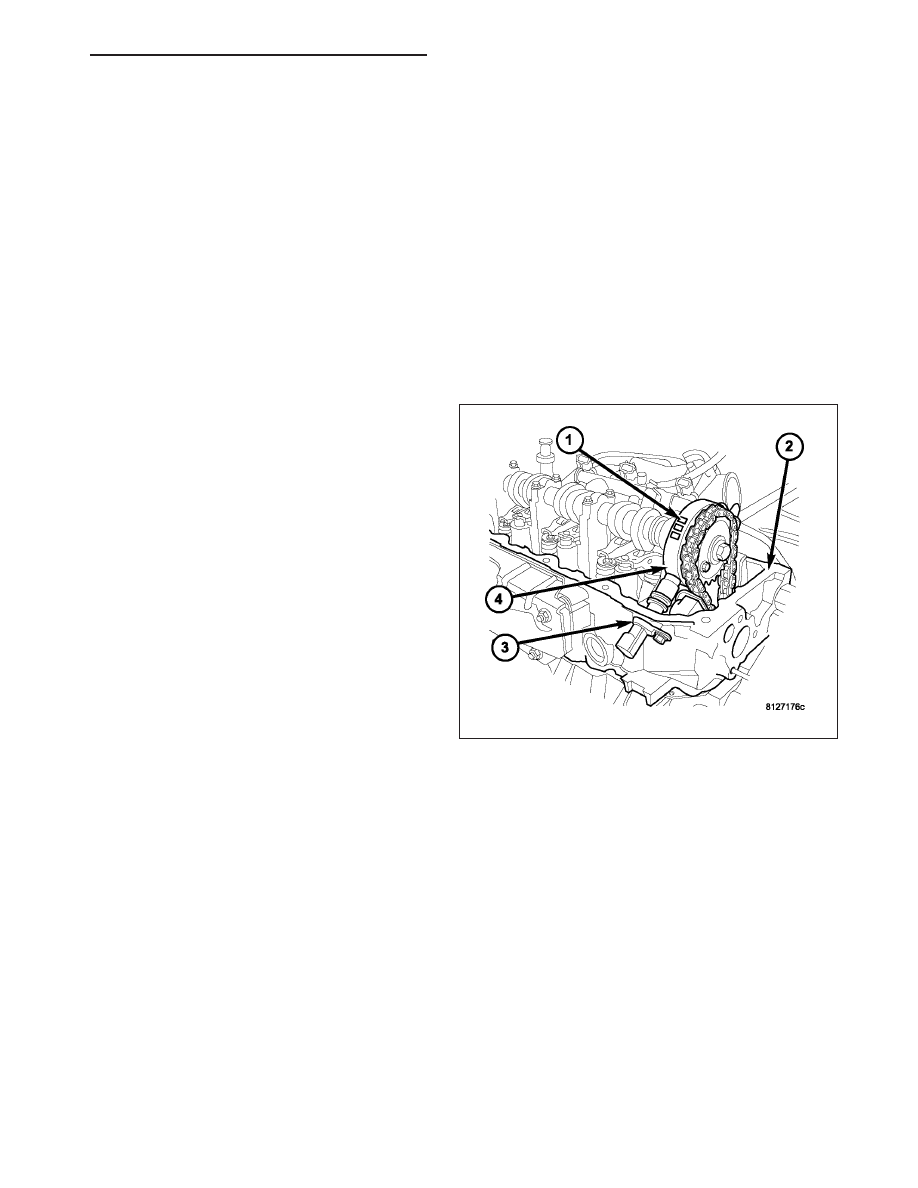
OPERATION
3.7L V-6
The Camshaft Position Sensor (CMP) sensor on the
3.7L V-6 engine (3) contains a hall effect device
referred to as a sync signal generator. A rotating target
wheel (tonewheel) for the CMP is located (4) at the
front of the camshaft for the right cylinder head (2).
This sync signal generator detects notches (1) located
on a tonewheel. As the tonewheel rotates, the notches
pass through the sync signal generator. The signal
from the CMP sensor is used in conjunction with the
Crankshaft Position Sensor (CKP) to differentiate
between fuel injection and spark events. It is also
used to synchronize the fuel injectors with their
respective cylinders.
When the leading edge of the tonewheel notch enters
the tip of the CMP, the interruption of magnetic field
causes the voltage to switch high, resulting in a sync
signal of approximately 5 volts.
When the trailing edge of the tonewheel notch leaves
then tip of the CMP, the change of the magnetic field
causes the sync signal voltage to switch low to 0
volts.
ND
IGNITION SYSTEM - SERVICE INFORMATION
8I - 9
Нет комментариевНе стесняйтесь поделиться с нами вашим ценным мнением.
Текст