Dodge Dakota (ND). Manual — part 1114
C1405- TRANSFER CASE RANGE POSITION SENSOR CIRCUIT HIGH (CONTINUED)
10.
INTERMITTENT WIRING AND CONNECTORS
The conditions necessary to set this DTC are not present at this time.
Using the wiring diagram/schematic as a guide, inspect the wiring and connectors.
While monitoring the scan tool data relative to this circuit, wiggle test the wiring and connectors.
Look for the data to change or for the DTC to reset during the wiggle test.
Were any problems found?
Yes
>> Repair as necessary.
Perform the TRANSFER CASE VERIFICATION TEST-VER 1. (Refer to 8 - ELECTRICAL/ELECTRONIC
CONTROL MODULES/TRANSFER CASE CONTROL MODULE - DIAGNOSIS AND TESTING)
No
>> Test complete.
21 - 848
TRANSFER CASE - ELECTRICAL DIAGNOSTICS
ND
C140B- TRANSFER CASE MOTOR CONTROL CIRCUIT LOW
ND
TRANSFER CASE - ELECTRICAL DIAGNOSTICS
21 - 849
C140B- TRANSFER CASE MOTOR CONTROL CIRCUIT LOW (CONTINUED)
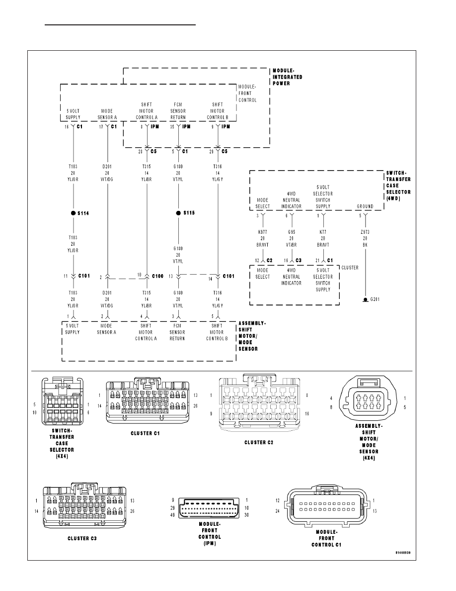
For a complete wiring diagram Refer to Section 8W
•
When Monitored:
Ignition on. Battery voltage between 9 and 16 volts.
•
Set Condition:
FCM detects low voltage on the Transfer Case Motor Control Circuit for 0.5 seconds.
Possible Causes
INTERMITTENT TRANSFER CASE MOTOR CONTROL CIRCUIT LOW
(T315) SHIFT MOTOR CONTROL A CIRCUIT OPEN
(T316) SHIFT MOTOR CONTROL B CIRCUIT OPEN
(T315) SHIFT MOTOR CONTROL A CIRCUIT SHORTED TO GROUND
(T316) SHIFT MOTOR CONTROL B CIRCUIT SHORTED TO GROUND
(T315) SHIFT MOTOR CONTROL A CIRCUIT SHORTED TO THE (T316) SHIFT MOTOR CONTROL B CIRCUIT
SHIFT MOTOR/MODE SENSOR ASSEMBLY
INTEGRATED POWER MODULE
FRONT CONTROL MODULE
Diagnostic Test
1.
DTC IS ACTIVE
Ignition on, engine not running.
With the scan tool, select View DTCs.
Is the status Active for this DTC?
Yes
>> Go to 2
No
>> Go to 16
2.
SHIFT MOTOR CIRCUIT RESISTANCE
Turn the ignition off.
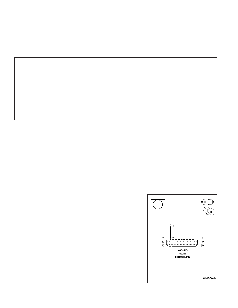
Remove the Front Control Module (FCM) from the Integrated Power
Module (IPM).
Measure the resistance between the (T315) Shift Motor Control A cir-
cuit and the (T316) Shift Motor Control B circuit at the FCM connector
in the IPM.
Is the resistance between 40 and 100 ohms?
Yes
>> Go to 15
No
>> Go to 3
21 - 850
TRANSFER CASE - ELECTRICAL DIAGNOSTICS
ND
C140B- TRANSFER CASE MOTOR CONTROL CIRCUIT LOW (CONTINUED)
3.
(T315) SHIFT MOTOR CONTROL A CIRCUIT OPEN
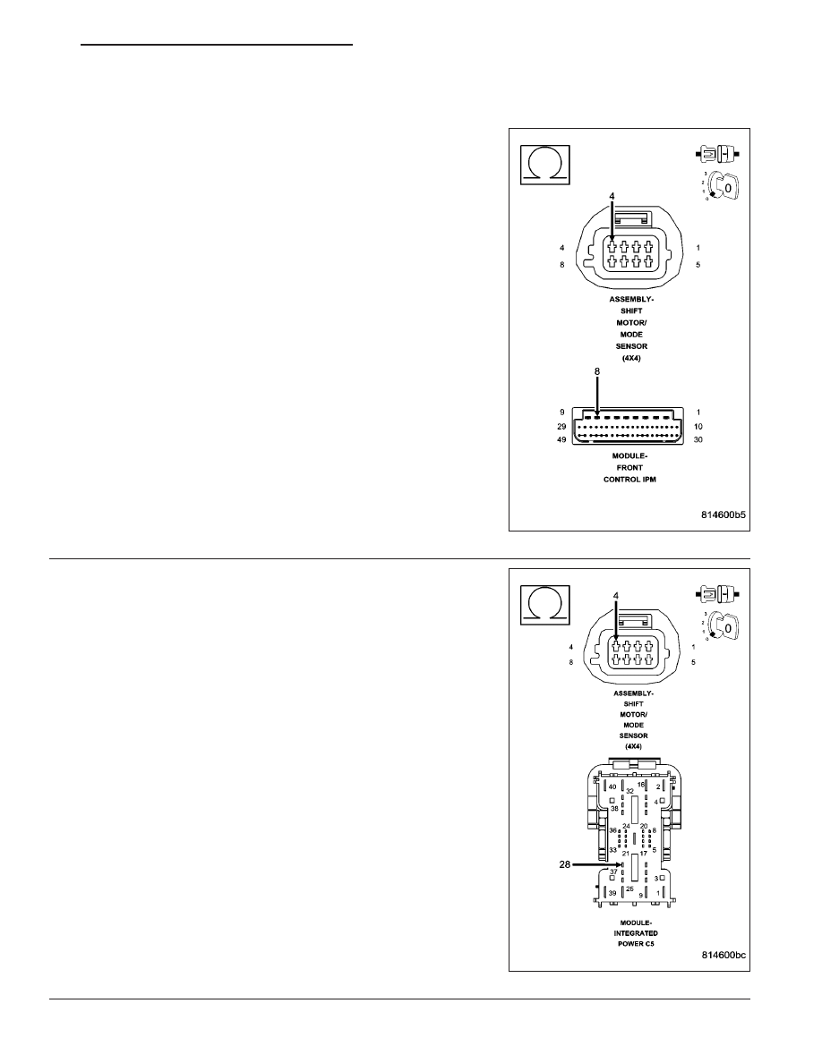
Disconnect the Shift Motor/Mode Sensor Assembly harness connector.
Measure the resistance of the (T315) Shift Motor Control A circuit from
the Shift Motor/Mode Sensor Assembly harness connector to the FCM
connector in the IPM.
Is the resistance above 5.0 ohms?
Yes
>> Go to 4
No
>> Go to 5
4.
(T315) SHIFT MOTOR CONTROL A CIRCUIT OPEN (IPM)
Disconnect the Integrated Power Module C5 harness connector.
Measure the resistance of the (T315) Shift Motor Control A circuit from
the Shift Motor/Mode Sensor Assembly harness connector to the Inte-
grated Power Module C5 harness connector.
Is the resistance above 5.0 ohms?
Yes
>> Repair the (T315) Shift Motor Control A circuit for an open.
Perform the TRANSFER CASE VERIFICATION TEST-
VER 1. (Refer to 8 - ELECTRICAL/ELECTRONIC CON-
TROL MODULES/TRANSFER CASE CONTROL MODULE
- DIAGNOSIS AND TESTING)
No
>> Go to 14
ND
TRANSFER CASE - ELECTRICAL DIAGNOSTICS
21 - 851
Нет комментариевНе стесняйтесь поделиться с нами вашим ценным мнением.
Текст