Dodge Dakota (ND). Manual — part 754
P0582-SPEED CONTROL VACUUM CONTROL CIRCUIT (CONTINUED)
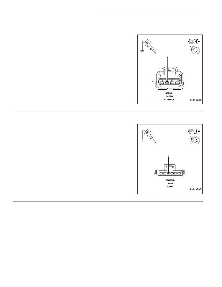
2.
(V30) S/C BRAKE SWITCH OUTPUT CIRCUIT
Turn the ignition off.
Disconnect the S/C Servo harness connector.
Ignition on, engine not running.
Using the scan tool, actuate the S/C Vacuum Solenoid.
Using a test light connected to ground, probe the (V30) S/C Brake
Switch Output circuit in the S/C Servo harness connector.
Does the test light illuminate brightly and flash on and off?
Yes
>> Go To 5
No
>> Go To 3
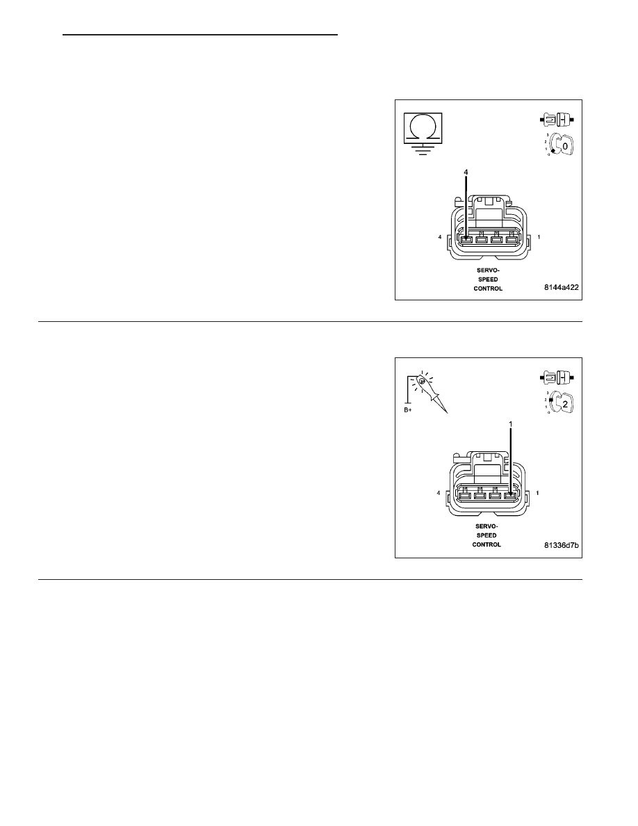
3.
(V32) S/C SUPPLY CIRCUIT
Turn the ignition off.
Connect the S/C Servo harness connector.
Disconnect the Stop Lamp Switch harness connector.
Ignition on, engine not running.
Using the scan tool, actuate the S/C Vacuum Solenoid.
Using a test light connected to ground, probe the (V32) S/C Supply
circuit in the Stop Lamp Switch harness connector.
Does the test light illuminate brightly?
Yes
>> Go To 4
No
>> Go To 8
9 - 554
ENGINE ELECTRICAL DIAGNOSTICS
ND
P0582-SPEED CONTROL VACUUM CONTROL CIRCUIT (CONTINUED)
4.
(Z155) S/C GROUND CIRCUIT OPEN
Turn the ignition off.
Disconnect the S/C Servo harness connector.
Measure the resistance between ground and the (Z155) S/C Ground
circuit at the S/C Servo harness connector.
Is the resistance below 5.0 ohms?
Yes
>> Go To 5
No
>> Repair the open in the (Z155) S/C Ground circuit.
Perform POWERTRAIN VERIFICATION TEST. (Refer to 9
- ENGINE - STANDARD PROCEDURE)
5.
SPEED CONTROL VACUUM SOLENOID
Ignition on, engine not running.
With the scan tool, actuate the Speed Control Vacuum Solenoid.
Using a 12-volt test light connected to battery voltage, probe the (V36)
S/C Vacuum Control circuit.
Does the test light illuminate brightly and flash on and off?
Yes
>> Replace the Speed Control Servo.
Perform POWERTRAIN VERIFICATION TEST. (Refer to 9
- ENGINE - STANDARD PROCEDURE)
No
>> Go To 6
ND
ENGINE ELECTRICAL DIAGNOSTICS
9 - 555
P0582-SPEED CONTROL VACUUM CONTROL CIRCUIT (CONTINUED)
6.
(V36) S/C VACUUM SOL CONTROL CIRCUIT OPEN
Turn the ignition off.
Disconnect the C3 PCM harness connector.
CAUTION: Do not probe the PCM harness connectors. Probing
the PCM harness connectors will damage the PCM terminals
resulting in poor terminal to pin connection. Install Miller Special
Tool #8815 to perform diagnosis.
Measure the resistance of the (V36) S/C Vacuum Sol Control circuit
from the Speed Control Servo harness connector to the appropriate
terminal of special tool # 8815.
Is the resistance below 5.0 ohms?
Yes
>> Go To 7
No
>> Repair the open/high resistance in the (V36) S/C Vacuum
Sol Control circuit.
Perform POWERTRAIN VERIFICATION TEST. (Refer to 9
- ENGINE - STANDARD PROCEDURE)
7.
(V36) SPEED CONTROL VACUUM SOLENOID CONTROL CIRCUIT SHORTED TO GROUND
Measure the resistance between ground and the (V36) S/C Vacuum
Solenoid Control circuit at the Speed Control Servo harness connector.
Is the resistance below 100 ohms?
Yes
>> Repair the short to ground in the (V36) S/C Vacuum Sol
Control circuit.
Perform POWERTRAIN VERIFICATION TEST. (Refer to 9
- ENGINE - STANDARD PROCEDURE)
No
>> Go To 10
9 - 556
ENGINE ELECTRICAL DIAGNOSTICS
ND

P0582-SPEED CONTROL VACUUM CONTROL CIRCUIT (CONTINUED)
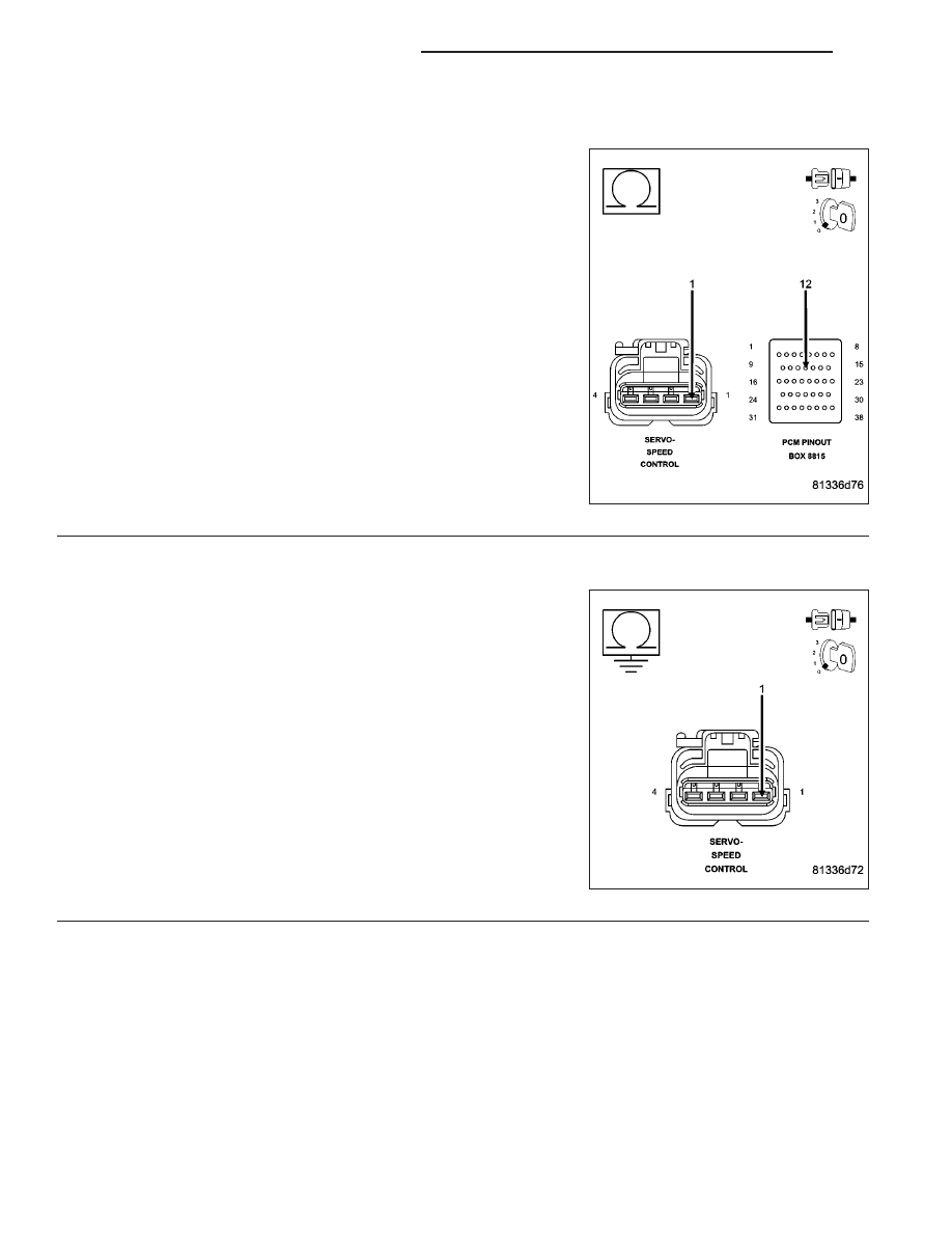
8.
(V32) S/C SUPPLY OPEN
Turn the ignition off.
Disconnect the C3 PCM harness connector.
CAUTION: Do not probe the PCM harness connectors. Probing
the PCM harness connectors will damage the PCM terminals
resulting in poor terminal to pin connection. Install Miller Special
Tool #8815 to perform diagnosis.
Measure the resistance of the (V32) S/C Supply circuit from the Stop
Lamp Switch harness connector to the appropriate terminal of special
tool #8815.
Is the resistance below 5.0 ohms?
Yes
>> Go To 9
No
>> Repair the open/high resistance in the (V32) S/C Supply
circuit.
Perform POWERTRAIN VERIFICATION TEST. (Refer to 9
- ENGINE - STANDARD PROCEDURE)
9.
(V32) S/C SUPPLY CIRCUIT SHORTED TO GROUND
Measure the resistance between ground and the (V32) S/C Supply cir-
cuit at the Speed Control Servo harness connector.
Is the resistance below 100 ohms?
Yes
>> Repair the short to ground in the (V32) S/C Supply circuit.
Perform POWERTRAIN VERIFICATION TEST. (Refer to 9
- ENGINE - STANDARD PROCEDURE)
No
>> Go To 10
10.
PCM
NOTE: Before continuing, check the PCM harness connector terminals for corrosion, damage, or terminal
push out. Repair as necessary.
Were there any problems found?
Yes
>> Repair as necessary.
Perform POWERTRAIN VERIFICATION TEST. (Refer to 9 - ENGINE - STANDARD PROCEDURE)
No
>> Replace and program the Powertrain Control Module per Service Information.
Perform POWERTRAIN VERIFICATION TEST. (Refer to 9 - ENGINE - STANDARD PROCEDURE)
ND
ENGINE ELECTRICAL DIAGNOSTICS
9 - 557
Нет комментариевНе стесняйтесь поделиться с нами вашим ценным мнением.
Текст