Dodge Dakota (ND). Manual — part 309
RELAY-FRONT FOG LAMP
DESCRIPTION
The front fog lamp relay is a conventional International
Standards Organization (ISO) micro relay. Relays con-
forming to the ISO specifications have common phys-
ical dimensions, current capacities, terminal patterns,
and terminal functions. This relay is contained within a
small, rectangular, molded plastic housing and is con-
nected to all of the required inputs and outputs
through five integral male spade-type terminals that
extend from the relay base plate.
The front fog lamp relay is located in the Power Dis-
tribution Center (PDC) in the engine compartment
near the battery. Refer to the layout label on the
underside of the PDC cover for specific relay cavity
assignment information. The front fog lamp relay can-
not be adjusted or repaired and, if faulty or damaged,
the unit must be replaced.
OPERATION
The front fog lamp relay is an electromechanical switch that uses a low current input from the Front Control Module
(FCM) (also referred to as the Integrated Power Module/IPM) to control a high current output to the front fog lamps.
Within the relay are an electromagnetic coil, a movable contact and two fixed contact points. A resistor is connected
in parallel with the coil, and helps to dissipate voltage spikes and electromagnetic interference that can be gener-
ated as the field of the relay coil collapses.
The movable common supply contact point is held against the fixed normally closed contact point by spring pres-
sure. When the relay coil is energized, an electromagnetic field is produced by the coil windings. This field draws
the movable contact away from the normally closed contact, and holds it against the normally open contact. When
the relay coil is de-energized, spring pressure returns the movable contact back against the normally closed contact.
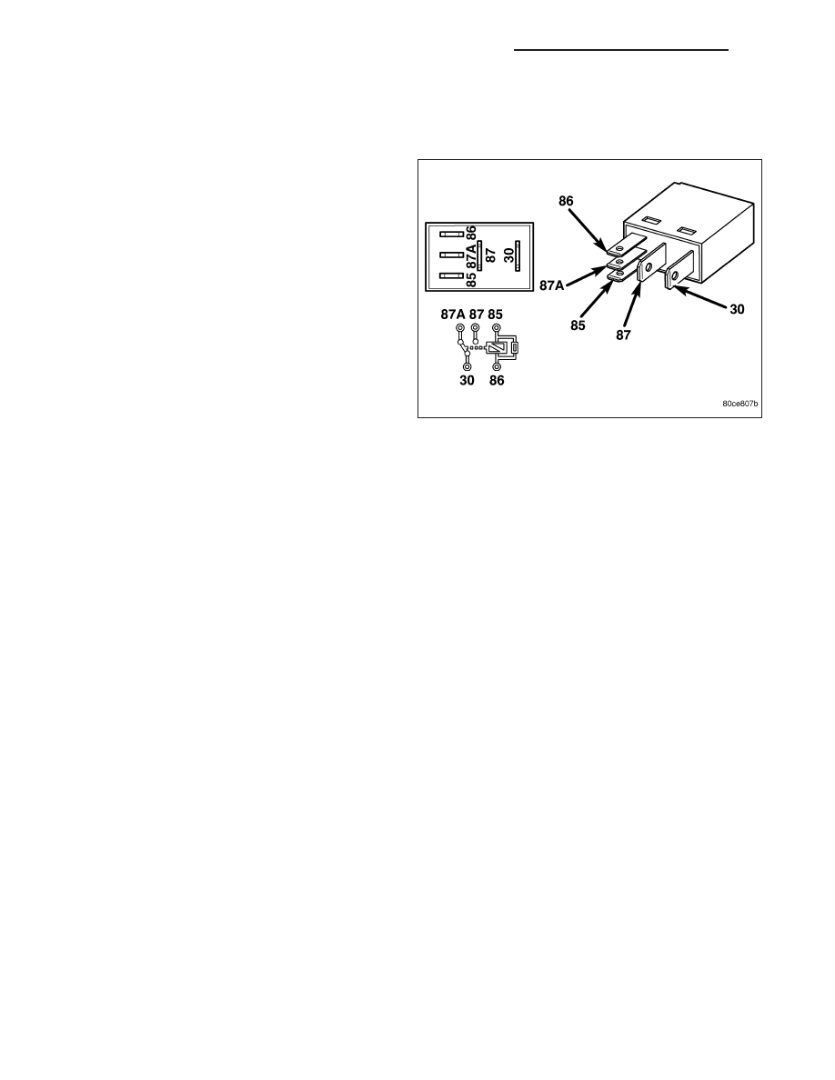
The inputs and outputs of the front fog lamp relay include:
•
Common Supply Terminal (30) - The common feed terminal is connected to a fused B(+) circuit at all times.
•
Coil Ground Terminal (85) - The coil ground terminal is connected to a fused B(+) circuit at all times.
•
Coil Battery Terminal (86) - The coil battery terminal is connected to a control output of the FCM through a
fog lamp relay control circuit. The FCM controls front fog lamp operation by controlling a ground path through
this circuit.
•
Normally Open Terminal (87) - The normally open terminal is connected to the front fog lamps through a fog
lamp relay output circuit and provides battery voltage to the front fog lamps whenever the relay is energized.
•
Normally Closed Terminal (87A) - The normally closed terminal is not connected to any circuit in this appli-
cation, but will have battery voltage present whenever the relay is de-energized.
The front fog lamp relay can be diagnosed using conventional diagnostic tools and methods. Refer to the appro-
priate wiring information.
LAMP-FRONT COMBINATION
STANDARD PROCEDURE
FRONT LAMP UNIT MOISTURE CLEARING
Some moisture accumulation inside a vented front lamp unit is normal. This normal moisture will appear as a fog-
ging on the inside of the lamp lens, similar to the fog that sometimes appears on the inside of a windshield. This
moisture may be removed by activating the headlamps on high beam for 15 minutes.
8L - 98
LAMPS/LIGHTING - EXTERIOR - SERVICE INFORMATION
ND
If water droplets larger than 1 millimeter in size have accumulated on the inside of the lamp lens, the front lamp unit
should be replaced.
REMOVAL
LAMP
1. Disconnect and isolate the battery negative cable.
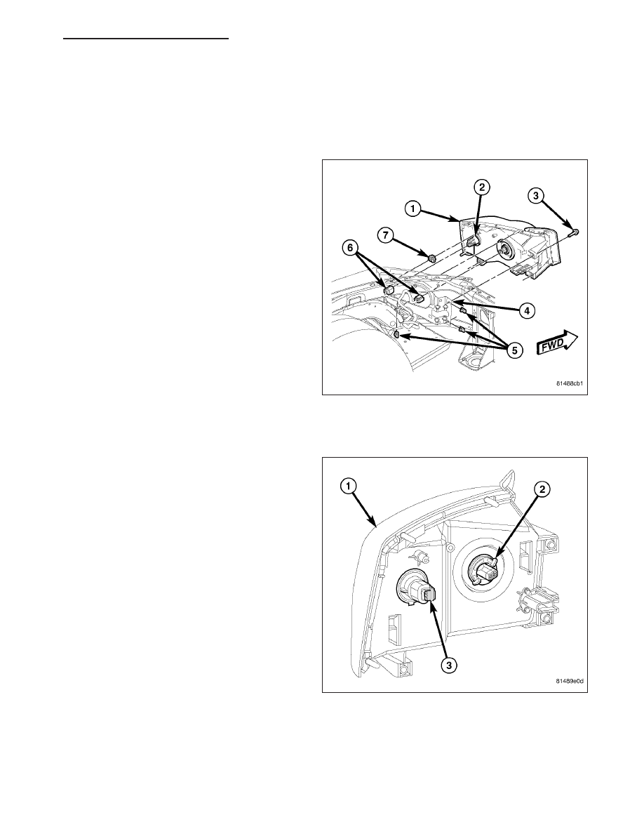
2. Remove the three screws (3) that secure the
inboard and lower mounts of the front lamp unit (1)
to the front fender headlamp bracket (4).
3. Grasp the lamp firmly and pull straight forward to
disengage the ball stud (2) on the back of the
upper outboard corner of the lamp from the plastic
grommet (7) in the fender bracket.
4. Pull the lamp away from the front fender far
enough to access and disconnect the two wire har-
ness connections (6) from the headlamp bulb and
the front park/turn signal/side marker bulb socket
on the back of the lamp.
5. Remove the front lamp unit from the fender.
BULB - PARK/TURN SIGNAL/SIDE MARKER
1. Disconnect and isolate the battery negative cable.
2. Remove the front lamp unit (1) from the front
fender. (Refer to 8 - ELECTRICAL/LAMPS/LIGHT-
ING
-
EXTERIOR/FRONT
LAMP
UNIT
-
REMOVAL).
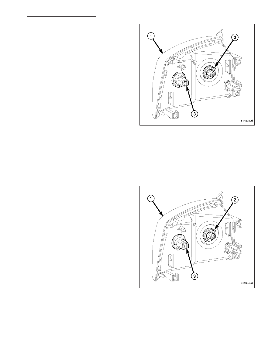
3. Firmly grasp the park/turn signal/side marker bulb
socket (3) on the back of the front lamp unit hous-
ing
and
rotate
it
counterclockwise
about
30
degrees to unlock it.
4. Pull the socket and bulb straight out from the
keyed opening in the housing.
5. Pull the base of the bulb straight out of the socket.
BULB - HEADLAMP
CAUTION: Do not contaminate the bulb glass by touching it with your fingers or by allowing it to contact
other oily surfaces. Shortened bulb life will result.
ND
LAMPS/LIGHTING - EXTERIOR - SERVICE INFORMATION
8L - 99

1. Disconnect and isolate the battery negative cable.
2. Remove the front lamp unit (1) from the front
fender. (Refer to 8 - ELECTRICAL/LAMPS/LIGHT-
ING
-
EXTERIOR/FRONT
LAMP
UNIT
-
REMOVAL).
3. Firmly grasp the headlamp bulb socket (2) on the
back of the front lamp unit housing and rotate it
counterclockwise about 30 degrees to unlock it.
4. Pull the socket and bulb unit straight out from the
keyed opening in the housing.
INSTALLATION
LAMP
1. Check to be certain that the three front lamp unit
U-nuts (5) and the plastic grommet (7) are in good
condition and properly positioned on the front
fender headlamp bracket (4).
2. Position the lamp close enough to the front fender
to access and reconnect the two wire harness con-
nections (6) to the headlamp bulb and the front
park/turn signal/side marker bulb socket on the
back of the lamp.
3. Rearrange the wire harnesses as necessary to pre-
vent them from becoming pinched between the
back of the lamp housing and the fender.
4. Align the ball stud (3) on the back of the upper out-
board corner of the lamp with the grommet in the
fender bracket.
5. Using hand pressure, press the lamp firmly and
evenly rearward until the ball stud snaps into the
grommet.
6. Install the three screws (3) that secure the inboard
and lower mounts of the lamp to the U-nuts on the fender bracket. Tighten the screws in Tighten the screws in
sequence beginning with the outboard lower, then the inboard upper and finally the inboard lower. Tighten the
screws to 7 N·m (65 in. lbs.).
7. Reconnect the battery negative cable.
8. Confirm proper headlamp alignment. (Refer to 8 - ELECTRICAL/LAMPS/LIGHTING - EXTERIOR - STANDARD
PROCEDURE - FRONT LAMP AIMING).
BULB - PARK/TURN SIGNAL/SIDE MARKER
CAUTION: Always use the correct bulb size and type for replacement. An incorrect bulb size or type may
overheat and cause damage to the lamp, the socket and/or the lamp wiring.
8L - 100
LAMPS/LIGHTING - EXTERIOR - SERVICE INFORMATION
ND
1. Align the base of the bulb with the park/turn signal/
side marker bulb socket (3).
2. Push the bulb straight into the socket until the base
is firmly seated.
3. Align the socket and bulb with the keyed opening
on the back of the front lamp unit housing (1).
4. Insert the socket and bulb into the housing until the
socket is firmly seated.
5. Rotate the socket clockwise about 30 degrees to
lock it into place.
6. Reinstall the front lamp unit onto the front fender.
(Refer to 8 - ELECTRICAL/LAMPS/LIGHTING -
EXTERIOR/FRONT LAMP UNIT - INSTALLATION).
7. Reconnect the battery negative cable.
BULB - HEADLAMP
CAUTION: Always use the correct bulb size and type for replacement. An incorrect bulb size or type may
overheat and cause damage to the lamp, the socket and/or the lamp wiring.
CAUTION: Do not contaminate the bulb glass by touching it with your fingers or by allowing it to contact
other oily surfaces. Shortened bulb life will result.
1. Align the headlamp socket and bulb unit (2) with
the keyed opening on the back of the front lamp
unit housing (1).
2. Insert the socket and bulb into the housing until the
socket is firmly seated.
3. Rotate the socket clockwise about 30 degrees to
lock it into place.
4. Reinstall the front lamp unit onto the front fender.
(Refer to 8 - ELECTRICAL/LAMPS/LIGHTING -
EXTERIOR/FRONT LAMP UNIT - INSTALLATION).
5. Reconnect the battery negative cable.
ND
LAMPS/LIGHTING - EXTERIOR - SERVICE INFORMATION
8L - 101
Нет комментариевНе стесняйтесь поделиться с нами вашим ценным мнением.
Текст