Dodge Dakota (ND). Manual — part 117
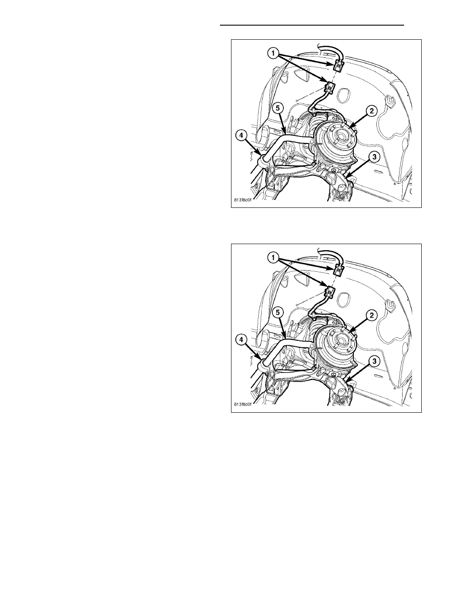
5. Remove the wiring from the clips and disconnect
the electrical connector (1).
INSTALLATION
1. Install the wiring to the clips and Reconnect the
electrical connector (1).
5 - 238
BRAKES - ABS SERVICE INFORMATION
ND
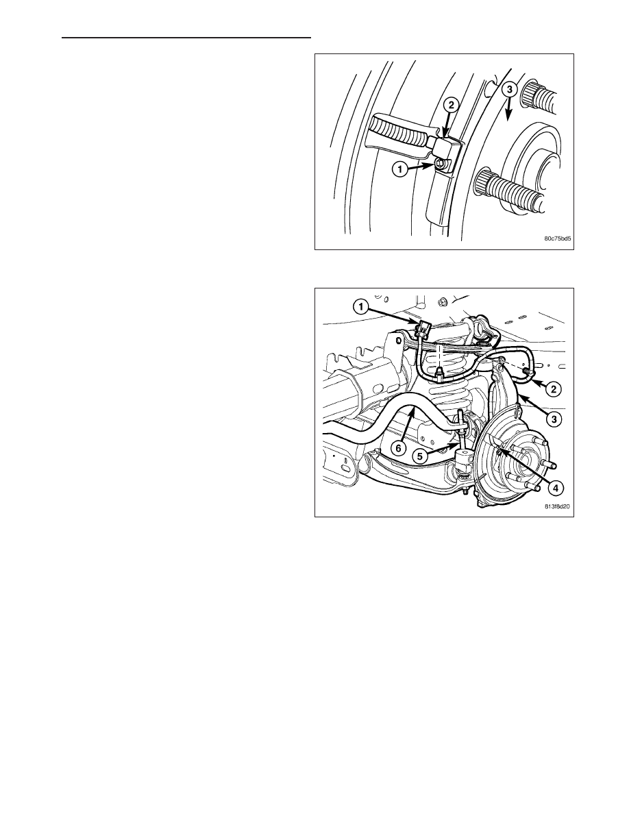
2. Install the wheel speed sensor (2) to the hub (3).
3. Install the wheel speed sensor mounting bolt (1) to
the hub (3). Tighten the bolt to 21 N·m (190 in.
lbs.).
4. Install the front rotor and brake caliper assembly
(Refer to 5 - BRAKES/HYDRAULIC/MECHANICAL/
ROTORS - INSTALLATION).
ND
BRAKES - ABS SERVICE INFORMATION
5 - 239
SENSOR-WHEEL SPEED-REAR
REMOVAL
1. Raise vehicle on hoist.
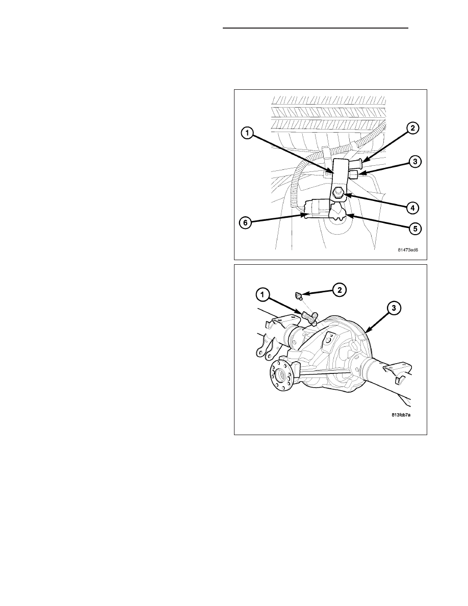
2. Remove brake line mounting nut (4) and remove
the brake line (3) from the sensor stud.
3. Remove the park brake cable (2) and bracket (1)
from the sensor stud.
4. Disconnect the electrical connector (6).
5. Remove mounting stud (2) from the sensor (5).
6. Remove sensor (1) from differential housing (3).
5 - 240
BRAKES - ABS SERVICE INFORMATION
ND
INSTALLATION
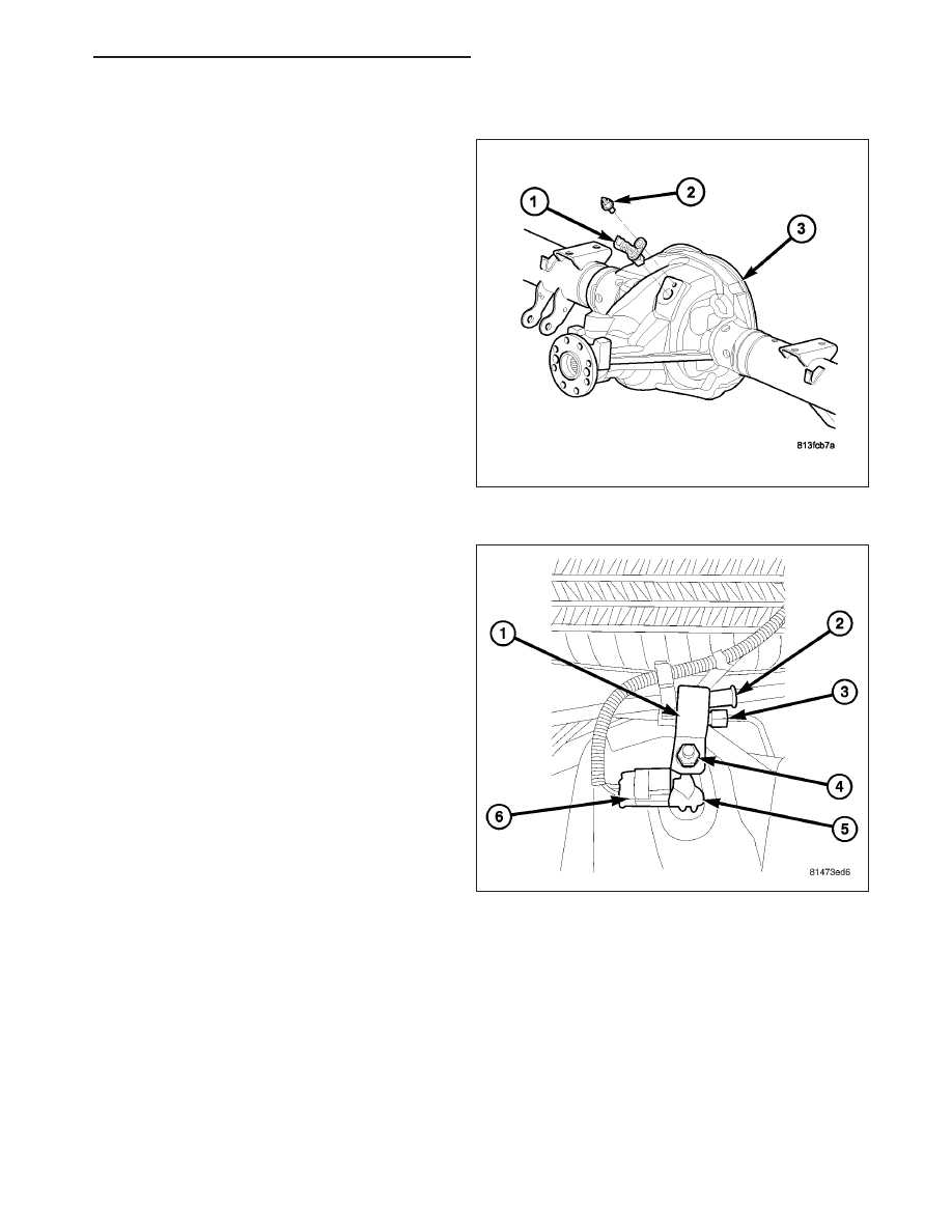
1. Connect harness to sensor (1). Be sure seal is
securely in place between sensor and wiring
connector.
2. Install O-ring on sensor (if removed).
3. Insert sensor (1) in differential housing (3).
4. Install the sensor mounting stud and tighten to 24
N·m (200 in. lbs.).
5. Reconnect the elctrical connector (6).
6. Install the brake line (3) on the sensor stud.
7. Install the park brake cable (2) and bracket (1) to
the stud and install the nut (4).
8. Lower vehicle.
SENSOR-G
DESCRIPTION
The G-sensor is located inside the ABS controller. The sensor is not a separate serviceable part from the controller.
HCU (HYDRAULIC CONTROL UNIT)
DESCRIPTION
The HCU consists of a valve body, pump motor, low pressure accumulators, inlet valves, outlet valves and noise
attenuators.
ND
BRAKES - ABS SERVICE INFORMATION
5 - 241
Нет комментариевНе стесняйтесь поделиться с нами вашим ценным мнением.
Текст