Dodge Dakota (ND). Manual — part 116
BRAKES - ABS SERVICE INFORMATION
TABLE OF CONTENTS
page
page
BRAKES - ABS SERVICE INFORMATION
. . . . . . . . . . . . . . . . . . . . . . . . 234
. . . . . . . . . . . . . . . . . . . . . . . . . . 234
. . . . . . . . . . . . . . . . 235
. . . . . . . . . . . . . . . . . . . . . 235
SENSOR-WHEEL SPEED - FRONT
. . . . . . . . . . . . . . . . . . . . . . . . . . 236
. . . . . . . . . . . . . . . . . . . . . . . . . . . . 237
. . . . . . . . . . . . . . . . . . . . . . . . 238
SENSOR-WHEEL SPEED-REAR
. . . . . . . . . . . . . . . . . . . . . . . . . . . . 240
. . . . . . . . . . . . . . . . . . . . . . . . 241
SENSOR-G
. . . . . . . . . . . . . . . . . . . . . . . . 241
HCU (HYDRAULIC CONTROL UNIT)
. . . . . . . . . . . . . . . . . . . . . . . . 241
. . . . . . . . . . . . . . . . . . . . . . . . . . 242
. . . . . . . . . . . . . . . . . . . . . . . . . . . . 242
. . . . . . . . . . . . . . . . . . . . . . . . 243
BRAKES - ABS SERVICE INFORMATION
DESCRIPTION
Rear Wheel Antilock (RWAL) brake system. The RWAL brake system is designed to prevent rear wheel lock-up
under heavy braking conditions on virtually all types of road surfaces. RWAL braking is desirable because a vehicle
which is stopped without locking the wheels will retain directional stability. This allows the driver to retain greater
control of the vehicle during braking.
The RWAL components include:
•
RWAL Valve
•
Antilock Brake Module (ABM)
•
Rear Wheel Speed Sensor (WSS)
OPERATION
When the brakes are applied, hydraulic fluid is routed from the master cylinder’s secondary circuit, to the RWAL
valve. From there hydraulic fluid is routed to the rear brake wheel cylinders. The Controller Antilock Brake monitors
rear wheel speed through the rear wheel speed sensor. If a wheel is about to lock-up, the ABM signals the RWAL
valve. The RWAL valve modulates the hydraulic brake pressure to the rear wheels to prevent wheel lock-up.
NORMAL BRAKING
During light brake application, rear wheel deceleration is not sufficient to activate the antilock system components.
During a normal stop hydraulic brake fluid flows unrestricted to the rear wheel cylinders to stop the vehicle. The
antilock solenoid valves are inactive. The isolation valve is open and the dump valve is closed allowing normal fluid
flow to the rear wheel cylinders.
REAR WHEEL ANTILOCK BRAKING
If the ABM senses impending rear wheel lock-up, it will energize the isolation solenoid. This prevents a further
increase of driver induced brake pressure to the rear wheels. If this initial action is not enough to prevent rear wheel
lock-up, the ABM will momentarily energize a dump solenoid. This opens the dump valve to vent a small amount of
isolated rear brake pressure to an accumulator. The action of fluid moving to the accumulator reduces the isolated
brake pressure at the wheel cylinders. The dump (pressure venting) cycle is limited to very short time periods (mil-
liseconds). The ABM will pulse the dump valve until rear wheel deceleration reaches the desired slip rate pro-
grammed into the ABM. The system will switch to normal braking once wheel locking tendencies are no longer
present.
5 - 234
BRAKES - ABS SERVICE INFORMATION
ND

DIAGNOSIS AND TESTING
ANTILOCK BRAKE SYSTEM
Diagnosis of base brake conditions which are mechanical in nature should be performed first. This includes brake
noise, lack of power assist, parking brake, or vehicle vibration during normal braking.
The Anitilock brake system performs several self-tests every time the ignition switch is turned on and the vehicle is
driven. The ABM monitors the system inputs and outputs circuits to verify the system is operating properly. If the
ABM senses a malfunction in the system it will set a DTC into memory and trigger the warning lamp.
NOTE: The scan tool is used to diagnose the Anitlock Braking System. For test procedures refer to the
Chassis Diagnostic Manual.
STANDARD PROCEDURE
ABS BRAKE BLEEDING
ABS system bleeding requires conventional bleeding methods plus use of the scan tool. The procedure involves
performing a base brake bleeding, followed by use of the scan tool to cycle and bleed the HCU pump and sole-
noids. A second base brake bleeding procedure is then required to remove any air remaining in the system.
1. Perform base brake bleeding, (Refer to 5 - BRAKES - STANDARD PROCEDURE) OR (Refer to 5 - BRAKES -
STANDARD PROCEDURE).
2. Connect scan tool to the Data Link Connector.
3. Select ANTILOCK BRAKES, followed by MISCELLANEOUS, then ABS BRAKES. Follow the instructions dis-
played. When scan tool displays TEST COMPLETE, disconnect scan tool and proceed.
4. Perform base brake bleeding a second time, (Refer to 5 - BRAKES - STANDARD PROCEDURE) OR (Refer to
5 - BRAKES - STANDARD PROCEDURE).
5. Top off master cylinder fluid level and verify proper brake operation before moving vehicle.
SPECIFICATIONS
TORQUE CHART
TORQUE SPECIFICATIONS
DESCRIPTION
N·m
Ft. Lbs.
In. Lbs.
HCU Assembly
Mounting Bolts
15
11
—
ABM Mounting Screws
6
—
53
ABS Assembly
Brake Line Fittings
19
—
170
Wheel Speed Sensors
Front Sensor Bolt
21
—
190
Rear Wheel Speed Sensor
Mounting Bolt
24
—
200
G-Sensor
With (TCS)
5.6
—
50
ND
BRAKES - ABS SERVICE INFORMATION
5 - 235
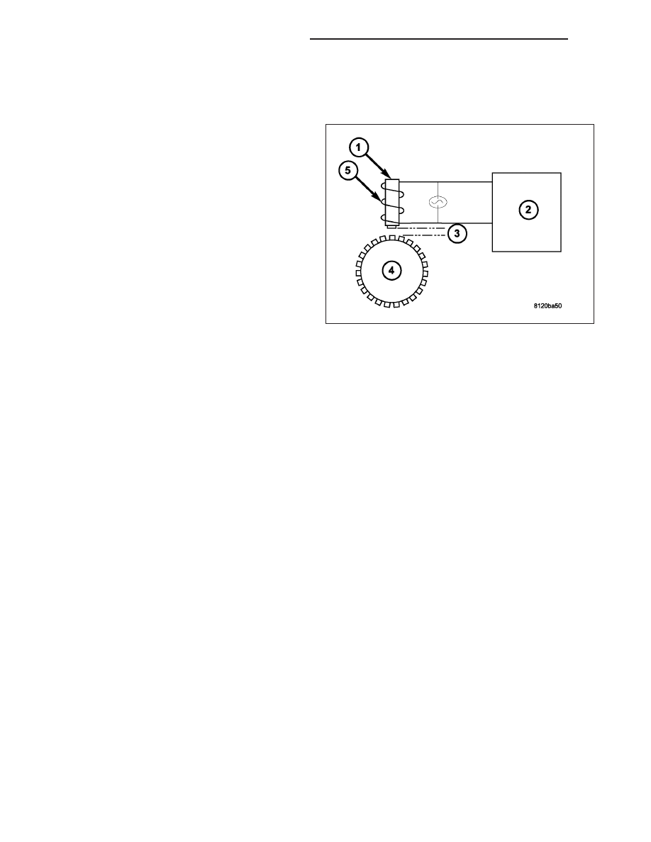
SENSOR-WHEEL SPEED - FRONT
OPERATION
The Wheel Speed Sensor consists of a magnet (1)
surrounded by windings from a single strand of wire
(5). The sensor sends a small AC signal to the ABM.
This signal is generated by magnetic induction. The
magnetic induction is created when a toothed sensor
ring (exciter ring or tone wheel) (4) passes the station-
ary magnetic WSS.
When the ring gear is rotated, the exciter ring (4)
passes the tip of the WSS. As the exciter ring tooth
approaches the tip of the WSS, the magnetic lines of
force expand, causing the magnetic field to cut across
the sensor’s windings (5). This, in turn causes current
to flow through the WSS circuit in one direction. When
the exciter ring tooth moves away from the sensor tip,
the magnetic lines of force collapse cutting the wind-
ing in the opposite direction. This causes the current
to flow in the opposite direction. Every time a tooth of
the exciter ring passes the tip of the WSS, an AC signal is generated current. Each AC signal (positive to negative
signal or squarewave) is interpreted by the ABM. It then compares the frequency of the sinewave to a time value to
calculate vehicle speed. The ABM continues to monitor the frequency to determine a deceleration rate that would
indicate a possible wheel-locking tendency.
The signal strength of any magnetic induction sensor is directly affected by:
•
Magnetic field strength; the stronger the magnetic field, the stronger the signal
•
Number of windings in the sensor; more windings provide a stronger signal
•
Exciter ring speed; the faster the exciter ring/tone wheel rotates, the stronger the signal will be
•
Distance (3) “air gap” between the exciter ring teeth and WSS; the closer the WSS is to the exciter ring/tone
wheel, the stronger the signal will be.
The WSS is not adjustable. A clearance specification has been established for manufacturing tolerances. If the
clearance is not within these specifications, then either the WSS or other components may be damaged. The clear-
ance between the WSS and the exciter ring is 0.005 – 0.050 in.
The assembly plant performs a “Rolls Test” on every vehicle that leaves the assembly plant. One of the test per-
formed is a test of the WSS. To properly test the sensor, the assembly plant connects test equipment to the Data
Link Connector (DLC). This connector is located to the right of the steering column and attached to the lower portion
of the instrument panel. The rolls test terminal is spliced to the WSS circuit. The vehicle is then driven on a set of
rollers and the WSS output is monitored for proper operation.
5 - 236
BRAKES - ABS SERVICE INFORMATION
ND
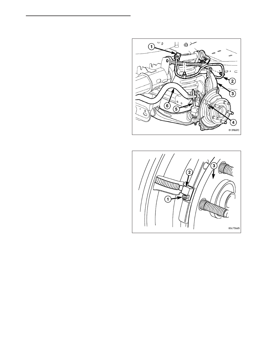
REMOVAL
1. Raise and support the vehicle.
2. Remove the front rotor and caliper adapter. (Refer
to 5 - BRAKES/HYDRAULIC/MECHANICAL/RO-
TORS - REMOVAL).
3. Remove the wheel speed sensor mounting bolt (1)
from the hub (3).
4. Remove the wheel speed sensor (2) from the hub
(3).
ND
BRAKES - ABS SERVICE INFORMATION
5 - 237
Нет комментариевНе стесняйтесь поделиться с нами вашим ценным мнением.
Текст