Dodge Dakota (ND). Manual — part 867

7. Install
both
secondary
chains
onto
the
idler
sprocket. Align two plated links on the secondary
chains to be visible through the two lower openings
on the idler sprocket (4 o’clock and 8 o’clock).
Once the secondary timing chains are installed,
position special tool 8515 (6) to hold chains in
place for installation.
8. Align primary chain double plated links with the tim-
ing mark at 12 o’clock (1) on the idler sprocket.
Align the primary chain single plated link with the
timing mark at 6 o’clock on the crankshaft sprocket
(3).
9. Lubricate idler shaft and bushings with clean
engine oil.
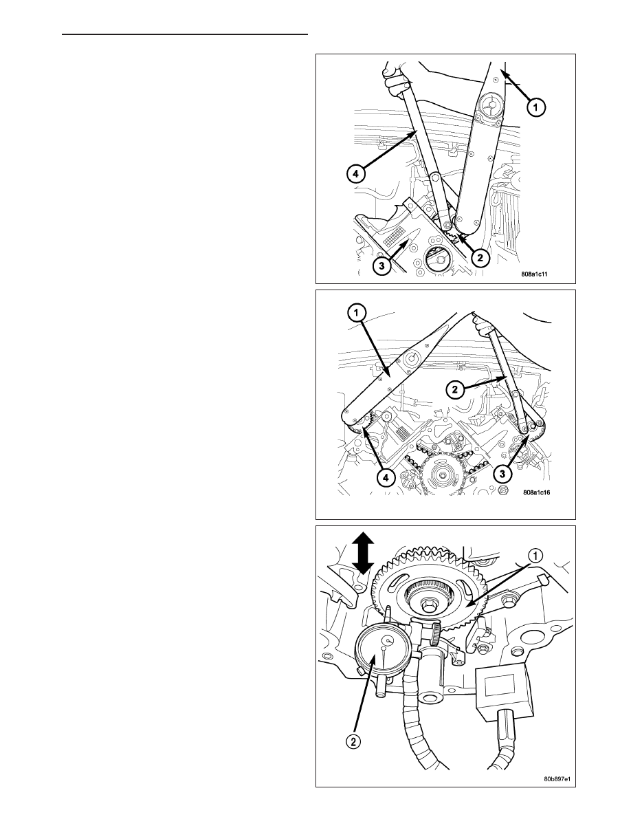
10. Install all chains, crankshaft sprocket, and idler
sprocket as an assembly. After guiding both sec-
ondary chains through the block and cylinder
head openings, affix chains with a elastic strap or
the equivalent, This will maintain tension on
chains to aid in installation.
NOTE: It will be necessary to slightly rotate cam-
shafts for sprocket installation.
11. Align left camshaft sprocket “L” dot to plated link
on chain.
12. Align right camshaft sprocket “R” dot to plated link
on chain.
CAUTION: Remove excess oil from the camshaft
sprocket bolt. Failure to do so can result in over-torque of bolt resulting in bolt failure.
13. Remove Special Tool 8515, then attach both sprockets to camshafts. Remove excess oil from bolts, then Install
sprocket bolts, but do not tighten at this time.
14. Verify that all plated links are aligned with the marks on all sprockets and the “V8” marks on camshaft sprockets
are at the 12 o’clock position.
CAUTION: Ensure the plate between the left secondary chain tensioner and block is correctly installed.
15. Install both secondary chain tensioners. Tighten bolts to 28 N·m (250 in. lbs.).
NOTE: Left and right secondary chain tensioners are not common.
16. Before installing idler sprocket bolt, lubricate washer with oil, and tighten idler sprocket assembly retaining bolt
to 34 N·m (25 ft. lbs.).
17. Remove all locking pins (3) from tensioners.
CAUTION: After pulling locking pins out of each tensioner, DO NOT manually extend the tensioner(s)
ratchet. Doing so will over tension the chains, resulting in noise and/or high timing chain loads.
9 - 1006
ENGINE - 4.7L SERVICE INFORMATION
ND
18. Using Special Tool 6958, Spanner with Adaptor
Pins 8346, tighten left (3) and right (4), camshaft
sprocket bolts to 122 N·m (90 ft. lbs.).
19. Rotate engine two full revolutions. Verify timing
marks are at the follow locations:
•
primary chain idler sprocket dot is at 12 o’clock
•
primary chain crankshaft sprocket dot is at 6
o’clock
•
secondary chain camshaft sprockets “V8” marks
are at 12 o’clock
20. Lubricate all three chains with engine oil.
21. After installing all chains, it is recommended that
the idler gear (1) end play be checked. The end
play must be within 0.10–0.25 mm (0.004–0.010
in.). If not within specification, the idler gear must
be replaced.
22. Install timing chain cover (Refer to 9 - ENGINE/
VALVE TIMING/TIMING BELT / CHAIN COV-
ER(S) - INSTALLATION) and crankshaft damper
(Refer to 9 - ENGINE/ENGINE BLOCK/VIBRA-
TION DAMPER - INSTALLATION).
23. Install cylinder head covers (Refer to 9 - ENGINE/
CYLINDER HEAD/CYLINDER HEAD COVER(S) -
INSTALLATION).
NOTE: Before installing threaded plug in right cyl-
inder head, the plug must be coated with sealant
to prevent leaks.
24. Coat the large threaded access plug with Mopar
T
Thread Sealant with Teflon, then install into the
right cylinder head and tighten to 81 N·m (60 ft.
lbs.).
25. Install the oil fill housing.
26. Install access plug in left cylinder head.
ND
ENGINE - 4.7L SERVICE INFORMATION
9 - 1007
27. Install power steering pump (Refer to 19 - STEERING/PUMP - INSTALLATION).
28. Install radiator fan shroud.
29. Fill cooling system (Refer to 7 - COOLING - STANDARD PROCEDURE).
30. Connect negative cable to battery.
SHAFT-IDLER
REMOVAL
1. Remove the primary and secondary timing chains and sprockets (Refer to 9 - ENGINE/VALVE TIMING/TIMING
BELT/CHAIN AND SPROCKETS - REMOVAL) .
NOTE: To remove the idler shaft, it is necessary to tap threads into the shaft, to install the removal tool.
2. Using a 12 mm X 1.75 tap, cut threads in the idler shaft center bore.
3. Cover the radiator core with a suitable cover.
CAUTION: Use care when removing the idler shaft, Do not strike the radiator cooling fins with the slide
hammer.
4. Using Special Tool 8517 Slide Hammer, remove the idler shaft.
INSTALLATION
1. Thoroughly clean the idler shaft bore.
2. Position the idler shaft in the bore.
NOTE: The two lubrication holes in the idler shaft do not require any special alignment.
NOTE: Before using the retaining bolt to install the idler shaft, coat the threads and the pilot on the idler
shaft, with clean engine oil.
3. Using the primary idler sprocket retaining bolt and washer, carefully draw the idler shaft into the bore until fully
seated.
4. Coat the idler shaft with clean engine oil.
5. Install the timing chains and sprockets (Refer to 9 - ENGINE/VALVE TIMING/TIMING BELT/CHAIN AND
SPROCKETS - INSTALLATION) .
9 - 1008
ENGINE - 4.7L SERVICE INFORMATION
ND
EXHAUST SYSTEM
TABLE OF CONTENTS
page
page
EXHAUST SYSTEM
. . . . . . . . . . . . . . . . . . . . . . . . . . 1
. . . . . . . . . . . . . . . . . . . . . . . . . . . . 2
. . . . . . . . . . . . . . . . . . . . . 2
CONVERTER-CATALYTIC
. . . . . . . . . . . . . . . . . . . . . . . . . . 3
. . . . . . . . . . . . . . . . . . . . . . . . . . . . 3
. . . . . . . . . . . . . . . . . . . . . . 4
. . . . . . . . . . . . . . . . . . . . . . . . . . . 4
. . . . . . . . . . . . . . . . . . . . . . 4
SHIELDS-HEAT
. . . . . . . . . . . . . . . . . . . . . . . . . . 5
. . . . . . . . . . . . . . . . . . . . . . . . . . . . 5
. . . . . . . . . . . . . . . . . . . . . . . . . . . . . . 5
. . . . . . . . . . . . . . . . . . . . . . . . . . 6
MUFFLER
. . . . . . . . . . . . . . . . . . . . . . . . . . 6
. . . . . . . . . . . . . . . . . . . . . . . . . . . . 6
. . . . . . . . . . . . . . . . . . . . . . . . . . . . . . 7
. . . . . . . . . . . . . . . . . . . . . . . . . . 7
TAILPIPE
. . . . . . . . . . . . . . . . . . . . . . . . . . 8
. . . . . . . . . . . . . . . . . . . . . . . . . . . . 8
. . . . . . . . . . . . . . . . . . . . . . . . . . . . . . 8
. . . . . . . . . . . . . . . . . . . . . . . . . . . 8
. . . . . . . . . . . . . . . . . . . . . . . . . . 9
EXHAUST SYSTEM
DESCRIPTION
CAUTION: Avoid application of rust prevention compounds or undercoating materials to exhaust system
floor pan exhaust heat shields. Light overspray near the edges is permitted. Application of coating will
result in excessive floor pan temperatures and objectionable fumes.
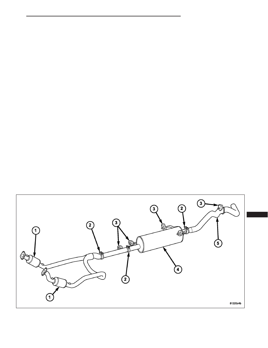
Exhaust System - 3.7L Engine - Typical
ND
EXHAUST SYSTEM
11 - 1
Нет комментариевНе стесняйтесь поделиться с нами вашим ценным мнением.
Текст