Dodge Dakota (ND). Manual — part 868

The gasoline engine exhaust system consists of engine exhaust manifolds, exhaust pipes , catalytic converter(s) (1),
extension pipe (if needed), exhaust heat shields, muffler (4) and exhaust tailpipe (5).
The exhaust system must be properly aligned to prevent stress, leakage and body contact. Minimum clearance
between any exhaust component and the body or frame is 25.4 mm (1.0 in.). If the system contacts any body panel,
it may amplify objectionable noises from the engine or body.
OPERATION
The exhaust system channels exhaust gases from the engine and away from the vehicle.
DIAGNOSIS AND TESTING
EXHAUST SYSTEM
EXHAUST SYSTEM DIAGNOSIS CHART
CONDITION
POSSIBLE CAUSE
CORRECTION
EXCESSIVE EXHAUST NOISE
1. Leaks at pipe joints.
1. Tighten clamps to specified
torque at leaking joints (Refer to 11
- EXHAUST SYSTEM -
SPECIFICATIONS).
2. Burned or blown out muffler.
2. Replace muffler assembly (Refer
to 11 - EXHAUST SYSTEM/
MUFFLER - REMOVAL). Check
exhaust system.
3. Burned or rusted-out exhaust
pipe.
3. Replace exhaust pipe (Refer to
11 - EXHAUST SYSTEM/EXHAUST
PIPE - REMOVAL).
4. Exhaust pipe leaking at manifold
flange.
4. Tighten connection attaching nuts
(Refer to 11 - EXHAUST SYSTEM -
SPECIFICATIONS).
5. Exhaust manifold cracked or
broken.
5. Replace exhaust manifold (Refer
to 9 - ENGINE/MANIFOLDS/
EXHAUST MANIFOLD -
REMOVAL).
6. Leak between exhaust manifold
and cylinder head.
6. Tighten exhaust manifold to
cylinder head stud nuts or bolts
(Refer to 9 - ENGINE -
SPECIFICATIONS).
7. Restriction in muffler or tailpipe.
7. Remove restriction, if possible.
Replace muffler or tailpipe, as
necessary.
8. Exhaust system contacting body
or chassis.
8. Re-align exhaust system to clear
surrounding components.
LEAKING EXHAUST GASES
1. Leaks at pipe joints.
1. Tighten/replace clamps at leaking
joints (Refer to 11 - EXHAUST
SYSTEM - SPECIFICATIONS).
11 - 2
EXHAUST SYSTEM
ND

SPECIFICATIONS
TORQUE SPECIFICATIONS
DESCRIPTION
N·m
Ft. Lbs.
In. Lbs.
Exhaust Clamp Nuts (All)
61
45
-
Exhaust Pipe to Manifold Nuts
34
25
-
Heat Shield Nuts
7
-
60
Muffler Hanger Bolts
23
-
200
Tailpipe Hanger Bolt
23
-
200
CONVERTER-CATALYTIC
DESCRIPTION
WARNING: THE NORMAL OPERATING TEMPERATURE OF THE EXHAUST SYSTEM IS VERY HIGH. THERE-
FORE, NEVER WORK AROUND OR ATTEMPT TO SERVICE ANY PART OF THE EXHAUST SYSTEM UNTIL IT
IS COOLED. SPECIAL CARE SHOULD BE TAKEN WHEN WORKING NEAR THE CATALYTIC CONVERTER.
THE TEMPERATURE OF THE CONVERTER RISES TO A HIGH LEVEL AFTER A SHORT PERIOD OF ENGINE
OPERATION TIME.
CAUTION: Avoid application of rust prevention compounds or undercoating materials to exhaust system
floor pan heat shields. Light overspray near the edges is permitted. Application of coating will result in
excessive floor pan temperatures and objectionable fumes.
The exhaust system uses a single muffler with a welded tailpipe.
The 50 State Emissions vehicles use two mini catalytic converters inline with the exhaust pipe below the exhaust
manifolds.
The exhaust manifolds are equipped with ball flange outlets to assure a tight seal and strain free connections.
The exhaust system must be properly aligned to prevent stress, leakage and body contact. If the system contacts
any body panel, it may amplify objectionable noises originating from the engine or body.
When inspecting an exhaust system, critically inspect for cracked or loose joints, stripped screw or bolt threads,
corrosion damage and worn, cracked or broken hangers. Replace all components that are badly corroded or dam-
aged. DO NOT attempt to repair.
When replacement is required, use original equipment parts (or their equivalent). This will assure proper alignment
and provide acceptable exhaust noise levels.
The basic exhaust system consists of exhaust manifold(s), exhaust pipe with oxygen sensors, catalytic converter(s),
heat shield(s), muffler and tailpipe.
OPERATION
The catalytic converter captures and burns any unburned fuel mixture exiting the combustion chambers during the
exhaust stroke of the engine. This process aids in reducing emissions output.
ND
EXHAUST SYSTEM
11 - 3
REMOVAL
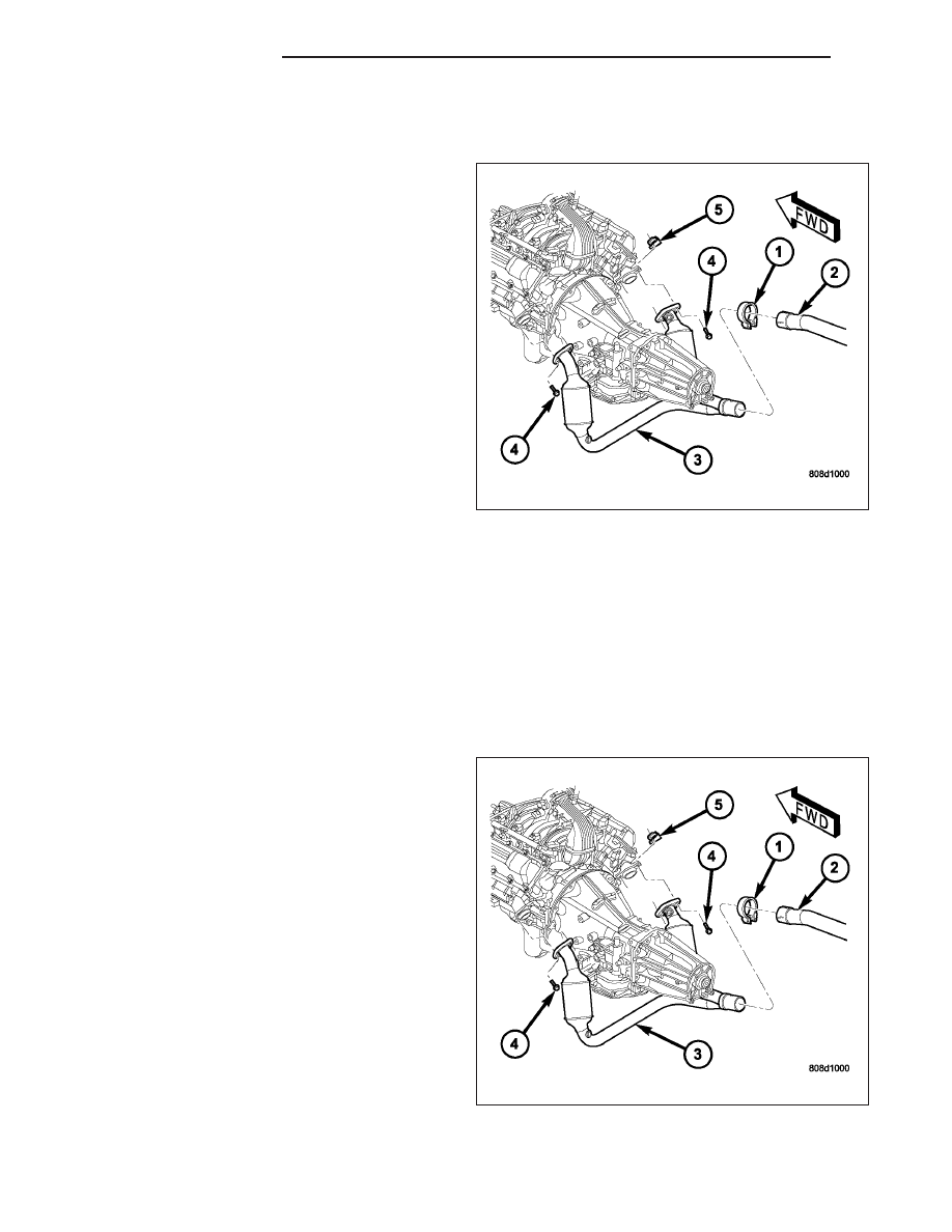
3.7L/4.7L ENGINE
CAUTION: When servicing or replacing exhaust
system components, disconnect the oxygen sen-
sor connector(s). Allowing the exhaust to hang by
the oxygen sensor wires will damage the harness
and/or sensor.
1. Raise and support the vehicle.
2. Saturate all exhaust bolts and nuts with Mopar
T
Rust Penetrant. Allow 5 minutes for penetration.
3. Disconnect the oxygen senor electrical connectors.
4. Remove the catalytic converter-to-manifold bolts
(5).
5. Remove the catalytic converter to the exhaust pipe
clamp (1).
6. If present, grind tack weld.
7. Remove the catalytic converter. You may have to
loosen up other sections of the exhaust system.
INSPECTION
Look at the stainless steel body of the converter, inspect for bulging or other distortion that could be a result of
overheating. If the converter has a heat shield attached make sure it is not bent or loose.
If you suspect internal damage to the catalyst, tapping the bottom of the catalyst with a rubber mallet may indicate
a damaged core.
INSTALLATION
3.7L/4.7L ENGINE
CAUTION: When servicing or replacing exhaust
system components, disconnect the oxygen sen-
sor connector(s). Allowing the exhaust to hang by
the oxygen sensor wires will damage the harness
and/or sensor.
NOTE: The band clamps are not reusable. After
removal, they must be replaced with new one.
1. Make sure the catalytic converter pipe is free of
burrs.
2. Insert the catalytic converter into the exhaust pipe.
3. Make sure the alignment tang is fully seated in the
alignment slot.
4. If other sections of the exhaust system where loos-
ened in removal, refer to that information for the
tightening procedures.
5. At the catalytic converter-to-extension pipe connec-
tion, install new clamp and nuts. Tighten the clamp nuts to 61 N·m (45 ft. lbs.) torque.
6. Lower the vehicle.
7. Start the engine, inspect for exhaust leaks. Repair exhaust leaks as necessary.
11 - 4
EXHAUST SYSTEM
ND

8. Check the exhaust system for contact with the body panels. Make the necessary adjustments, if necessary.
SHIELDS-HEAT
DESCRIPTION
There are two types of heat shields (1) used. One is
stamped steel the other is molded foil sheets. The
shields attach to the vehicle around the exhaust
system.
OPERATION
The heat shields prevent heat from the exhaust system from entering the passenger area and other areas where
the heat can cause damage to other components.
REMOVAL
1. Raise and support the vehicle.
2. Remove the screws and nuts holding the heat
shields (1) to the frame and floor pan. Be sure to
disconnect both oxygen sensor connectors.
3. Slide the heat shield (1) out around the exhaust
system.
ND
EXHAUST SYSTEM
11 - 5
Нет комментариевНе стесняйтесь поделиться с нами вашим ценным мнением.
Текст