Dodge Dakota (ND). Manual — part 714
P0401-EGR SYSTEM PERFORMANCE (CONTINUED)
For the Engine circuit diagram (Refer to 9 - ENGINE - SCHEMATICS AND DIAGRAMS).
For a complete wiring diagram Refer to Section 8W.
Theory of Operation
Exhaust gas recirculation is a method of reducing emissions of oxides of nitrogen. As the inert exhaust gas is recir-
culated, the mixture absorbs heat in the combustion chamber without interacting with the fuel/air mixture and
reduces the formation of NOx emissions. After the EGR monitor conditions are met, the EGR valve is turned on and
off momentarily. The EGR monitor calculated the difference in engine roughness from the EGR off condition to the
EGR condition. This engine combustion stability difference as measured by engine roughness is the measure of a
functional EGR system.
•
When Monitored:
Engine running for greater than two minutes with the Engine Coolant Temp greater than 70°C (158°F). EGR
active. Less than 8500 feet. Ambient temperature greater than -6°C (20°F).
•
Set Condition:
The PCM closes the EGR valve while monitoring the O2 Sensor signal. Once a closed EGR fueling sample
has been established the PCM then ramps in EGR and additional fueling while monitoring the O2 sensor sig-
nal in the open state. A fueling sample is again established. The PCM then compares the different O2 Sensor
signal readings (fueling samples). If a larger than expected variation is detected, a soft failure is recorded.
Three soft failures set a one trip failure. After two failed trips, a DTC is set and the MIL is illuminated.
Possible Causes
(Z958) EGR SOLENOID GROUND CIRCUIT OPEN
(K35) EGR SOLENOID CONTROL CIRCUIT SHORTED TO GROUND
(K35) EGR SOLENOID CONTROL CIRCUIT SHORTED TO BATTERY VOLTAGE
(K35) EGR SOLENOID CONTROL CIRCUIT OPEN
EGR SOLENOID ASSEMBLY
PCM
Always perform the Pre-Diagnostic Troubleshooting procedure before proceeding. (Refer to 9 - ENGINE -
DIAGNOSIS AND TESTING).
Diagnostic Test
1.
ACTIVE DTC
Ignition on, engine not running.
With a scan tool, read DTCs.
Is the DTC active at this time?
Yes
>> Go To 2
No
>> Refer to the INTERMITTENT CONDITION Diagnostic Procedure.
Perform POWERTRAIN VERIFICATION TEST. (Refer to 9 - ENGINE - STANDARD PROCEDURE)
9 - 394
ENGINE ELECTRICAL DIAGNOSTICS
ND
P0401-EGR SYSTEM PERFORMANCE (CONTINUED)
2.
EGR OPERATION
NOTE: If the vehicle is running rough at idle (scan tool not actuating) follow the yes path to continue.
Turn all accessories off.
Start the engine.
Allow the engine to reach normal operating temperature.
With the scan tool, enter Engine System Test, then EGR System Test.
Actuate the FLOW function in the EGR System Test.
Did the engine run rough or stall?
Yes
>> Go To 3
No
>> Go To 6
3.
EGR VALVE OPEN AT IDLE
Turn the ignition off.
Disconnect the EGR Solenoid Assembly harness connector.
Start engine. Attempt to allow the engine to idle.
Does the engine run rough or stall?
Yes
>> Inspect the EGR tube assembly. If OK, replace the EGR valve.
Perform POWERTRAIN VERIFICATION TEST. (Refer to 9 - ENGINE - STANDARD PROCEDURE)
No
>> Go To 4
4.
EGR VALVE ASSEMBLY INSPECTION
Inspect the EGR Assembly for the following.
Gasket(s) for leaking
Damage and/or holes in the EGR tube(s)
Carbon build up on or near the EGR pintle and passage ways.
Obstruction in the EGR tubes.
Were any problem found?
Yes
>> Repair or replace the EGR Assembly as necessary.
Perform POWERTRAIN VERIFICATION TEST. (Refer to 9 - ENGINE - STANDARD PROCEDURE)
No
>> Go To 5
ND
ENGINE ELECTRICAL DIAGNOSTICS
9 - 395
P0401-EGR SYSTEM PERFORMANCE (CONTINUED)
5.
(K35) EGR SOLENOID CONTROL CIRCUIT SHORTED TO BATTERY VOLTAGE
Turn the ignition off.
Disconnect the EGR Solenoid harness connector.
Ignition on, engine not running.
Measure the voltage on the (K35) EGR Solenoid Control circuit in the
EGR Solenoid connector.
Is the voltage above 1.0 volt?
Yes
>> Repair the short to battery voltage in the (K35) EGR Sole-
noid Control circuit.
Perform POWERTRAIN VERIFICATION TEST. (Refer to 9
- ENGINE - STANDARD PROCEDURE)
No
>> Go To 10
6.
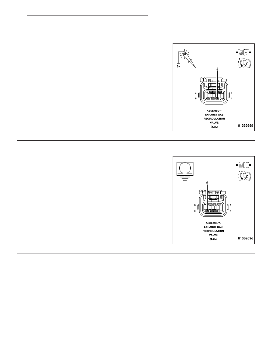
EGR SOLENOID ASSEMBLY
Disconnect the EGR Solenoid harness connector.
Using a 12-volt test light, jump across the (K35) EGR Solenoid Control
terminal and the (Z958) Ground terminal in the EGR Solenoid harness
connector.
With the scan tool, actuate the EGR solenoid.
Does the 12-volt test light flash on and off?
Yes
>> Inspect the tube(s) for obstructions and damage, repair as
necessary. Replace the EGR Solenoid Assembly.
Perform POWERTRAIN VERIFICATION TEST. (Refer to 9
- ENGINE - STANDARD PROCEDURE)
No
>> Go To 7
9 - 396
ENGINE ELECTRICAL DIAGNOSTICS
ND
P0401-EGR SYSTEM PERFORMANCE (CONTINUED)
7.
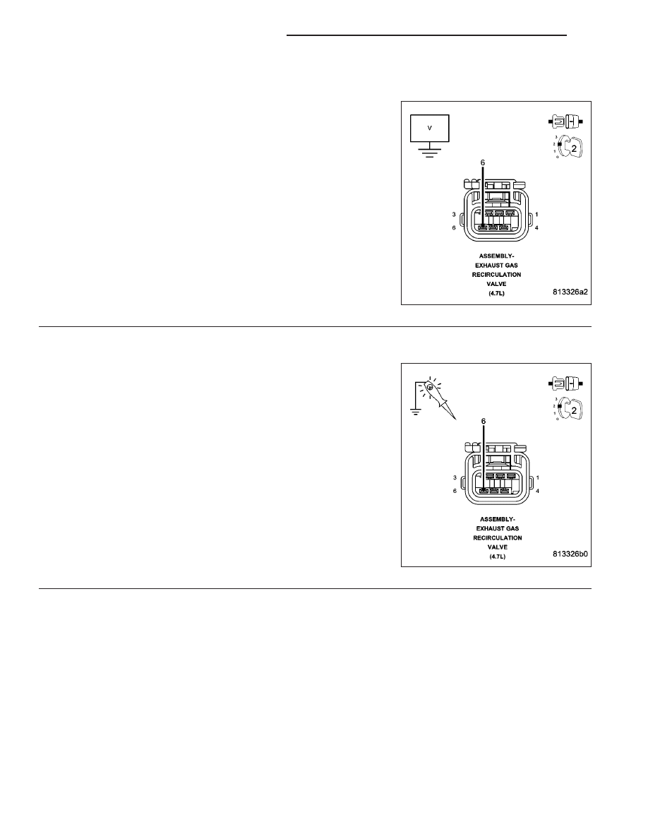
(Z958) EGR SOLENOID GROUND CIRCUIT OPEN
Turn the ignition off.
Using a 12-volt test light connected to battery voltage, probe the
(Z958) EGR Solenoid ground circuit in the EGR Solenoid harness con-
nector.
Does the 12-volt test light illuminate brightly?
Yes
>> Go To 8
No
>> Repair the open in the (Z958) EGR Solenoid ground cir-
cuit.
Perform POWERTRAIN VERIFICATION TEST. (Refer to 9
- ENGINE - STANDARD PROCEDURE)
8.
(K35) EGR SOLENOID CONTROL CIRCUIT SHORTED TO GROUND
Disconnect the C2 PCM harness connector.
Measure the resistance between ground and the (K35) EGR Solenoid
Control circuit in the EGR Solenoid harness connector.
Is the resistance below 100 ohms?
Yes
>> Repair the short to ground in the (K35) EGR Solenoid
Control circuirt.
Perform POWERTRAIN VERIFICATION TEST. (Refer to 9
- ENGINE - STANDARD PROCEDURE)
No
>> Go To 9
ND
ENGINE ELECTRICAL DIAGNOSTICS
9 - 397
Нет комментариевНе стесняйтесь поделиться с нами вашим ценным мнением.
Текст