Dodge Dakota (ND). Manual — part 17
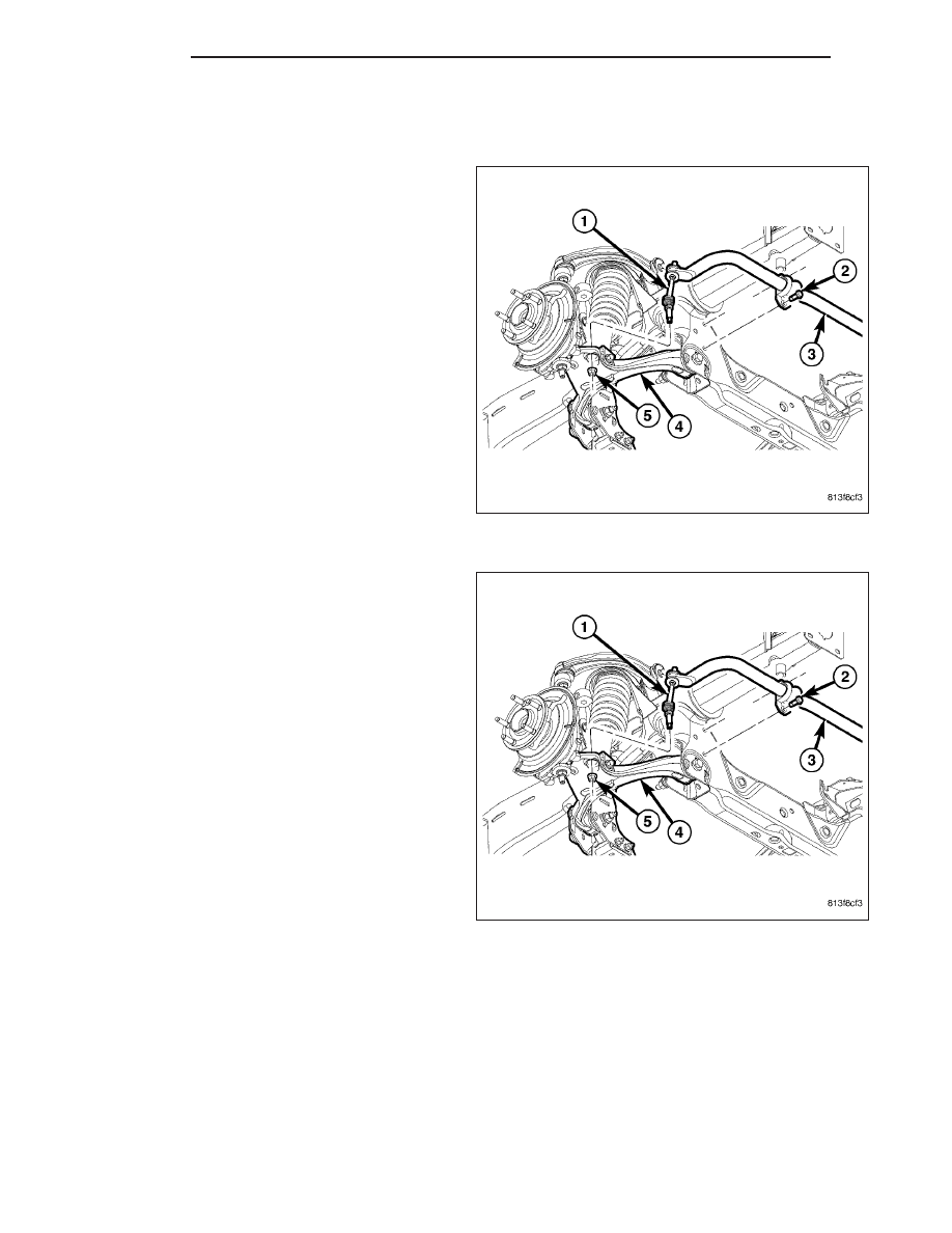
STABILIZER LINK
REMOVAL
1. Raise and support the vehicle.
2. Remove the lower nut (5).
3. Remove the upper nut, retainers and grommets
from the stabilizer bar (3).
4. Remove the stabilizer link (1) from the vehicle.
INSTALLATION
1. Install the stabilizer link (1) to the vehicle.
2. Install the retainers, grommets and upper nut to the
stabilizer bar (3) and Tighten to 37 N·m (27 ft. lbs.).
3. Install the lower nut (5) and Tighten to 169 N·m
(125 ft. lbs.).
4. Remove the support and lower the vehicle.
2 - 36
FRONT
ND
UPPER BALL JOINT
DIAGNOSIS AND TESTING
UPPER BALL JOINT
1. Raise the front of the vehicle. Place safety floor
stands under both lower control arms as far out-
board as possible. Lower the vehicle to allow the
stands to support some or all of the vehicle weight.
2. Remove the front tires.
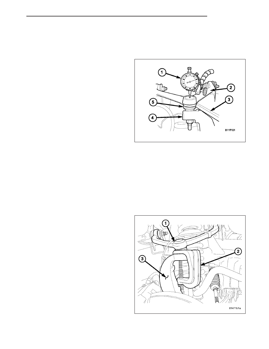
3. Mount a dial indicator (1) solidly to the frame and
then zero the dial indicator.
4. Position dial indicator plunger on the topside of the
upper ball joint (5).
NOTE: The dial indicator plunger must be perpen-
dicular to the machined surface of the ball joint.
NOTE: Use care not to pry or tear the ball joint
boot, when checking the free play.
5. Position a pry bar (3) between the steering knuckle (4) and the upper control arm (2). Pry upwards on the upper
control arm.
6. If the travel exceeds 0.5 mm (0.020 in.), replace the upper control arm since the upper ball joint is integral to the
arm (Refer to 2 - SUSPENSION/FRONT/UPPER CONTROL ARM - REMOVAL).
7. If the upper ball joint is within specs reinstall the front tires (Refer to 22 - TIRES/WHEELS/WHEELS - STAN-
DARD PROCEDURE).
UPPER CONTROL ARM
REMOVAL
1. Raise and support vehicle.
2. Remove wheel and tire assembly.
3. Remove the nut from upper ball joint.
4. Separate upper ball joint (1) from the steering
knuckle (3) with Remover 8677 (2).
CAUTION: When installing Remover 8677 (2) to
separate the ball joint, be careful not to damage
the ball joint seal.
ND
FRONT
2 - 37
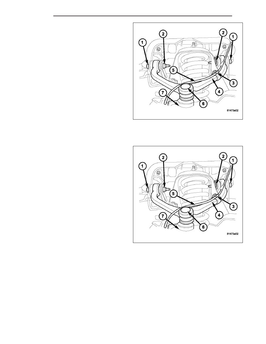
5. Remove the wheel speed sensor wire (5) from the
retaining brackets (3) to the upper control arm (4).
6. Remove the control arm pivot bolts(1) and nuts (2)
and remove control arm (4).
INSTALLATION
NOTE: All suspension components should be tighten with the weight of the vehicle on them (curb height).
1. Position the control arm (4) into the frame brackets.
Install bolts (1) and nuts (2). Tighten to 102 N·m
(75 ft. lbs.).
2. Reposition the wheel speed wire (5) into the retain-
ing brackets (3).
3. Insert ball joint (6) in steering knuckle (7) and
tighten ball joint nut to 75 N·m (55 ft. lbs.).
4. Install the wheel and tire assembly, (Refer to 22 - TIRES/WHEELS/WHEELS - STANDARD PROCEDURE).
5. Remove the support and lower vehicle.
6. Perform a wheel alignment, (Refer to 2 - SUSPENSION/WHEEL ALIGNMENT - STANDARD PROCEDURE).
2 - 38
FRONT
ND
REAR
TABLE OF CONTENTS
page
page
REAR
. . . . . . . . . . . . . . . . . . . . . . . . . 39
. . . . . . . . . . . . . . . . . . . . . . . . 40
. . . . . . . . . . . . . . . . . . . . . . 40
JOUNCE BUMPER
. . . . . . . . . . . . . . . . . . . . . . . . . . . . . 41
. . . . . . . . . . . . . . . . . . . . . . . . . 41
SHOCK
. . . . . . . . . . . . . . . . . . . . . . . . . . . . . 42
. . . . . . . . . . . . . . . . . . . . . . . . . 43
SPRING
. . . . . . . . . . . . . . . . . . . . . . . . . . . . . 45
. . . . . . . . . . . . . . . . . . . . . . . . . 46
STABILIZER LINK
. . . . . . . . . . . . . . . . . . . . . . . . . . . . . 49
. . . . . . . . . . . . . . . . . . . . . . . . . 50
STABILIZER BAR
. . . . . . . . . . . . . . . . . . . . . . . . . 50
. . . . . . . . . . . . . . . . . . . . . . . . . . . 50
. . . . . . . . . . . . . . . . . . . . . . . . . . . . . 51
. . . . . . . . . . . . . . . . . . . . . . . . . 52
REAR
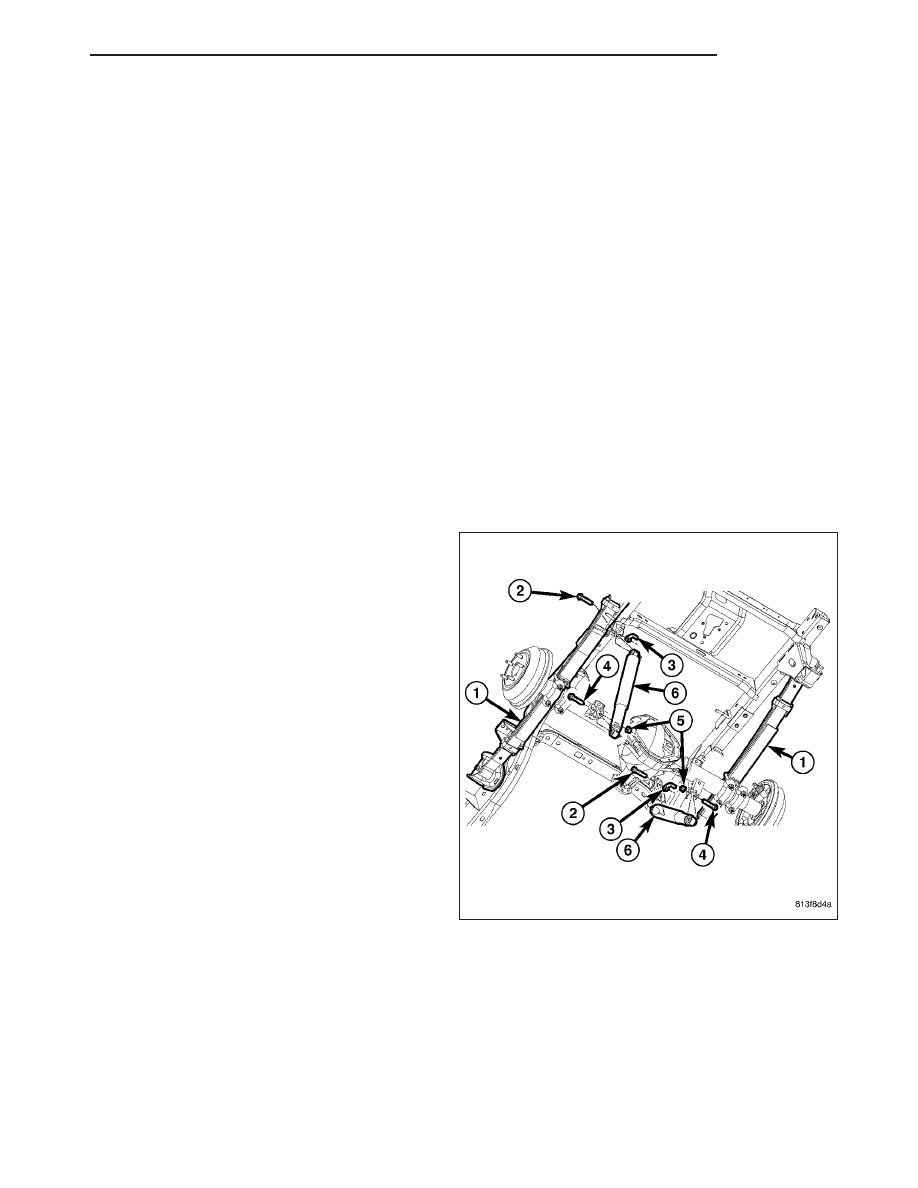
DESCRIPTION
The rear suspension is comprised of:
•
Shock Absorbers (6)
•
Jounce Bumpers
•
Stabilizer Bar
•
Stabilizer links
•
Leaf Springs (1)
•
Drive Axle
CAUTION: A vehicle should always be loaded so
the vehicle weight center-line is located immedi-
ately forward of the rear axle. Correct vehicle load-
ing provides proper front tire-to-road contact. This
results in maximum vehicle handling stability and
safety. Incorrect vehicle weight distribution can
cause excessive tire tread wear, spring fatigue or
failure, and erratic steering.
ND
REAR
2 - 39
Нет комментариевНе стесняйтесь поделиться с нами вашим ценным мнением.
Текст