Dodge Dakota (ND). Manual — part 16

INSTALLATION
NOTE: All suspension components should be tighten with the weight of the vehicle on them (curb height).
1. Install the upper part of the shock (2) into the
frame bracket.
2. Install the upper nuts (1). Tighten to 102 N·m (75 ft.
lbs.).
3. Install the lower part of the shock (2) into the lower
control arm shock bushing.
4. Position shock module clevis (2) to lower control
(6). Install bolt (4) so head of bolt is facing rear of
vehicle and hand start nut (3). Tighten the bolt (4)
& nut (5) to 81 N·m (60 ft. lbs.).
5. Install the stabilizer link lower nut (5) to the lower
control arm (6) (Refer to 2 - SUSPENSION/
FRONT/STABILIZER LINK - INSTALLATION).
6. Remove the support from the lower control arm outboard end.
7. Install the tire and wheel assembly (Refer to 22 - TIRES/WHEELS/WHEELS - STANDARD PROCEDURE).
8. Remove the support and lower the vehicle.
2 - 32
FRONT
ND

SPRING
REMOVAL
1. Remove the shock (Refer to 2 - SUSPENSION/
FRONT/SHOCK - REMOVAL).
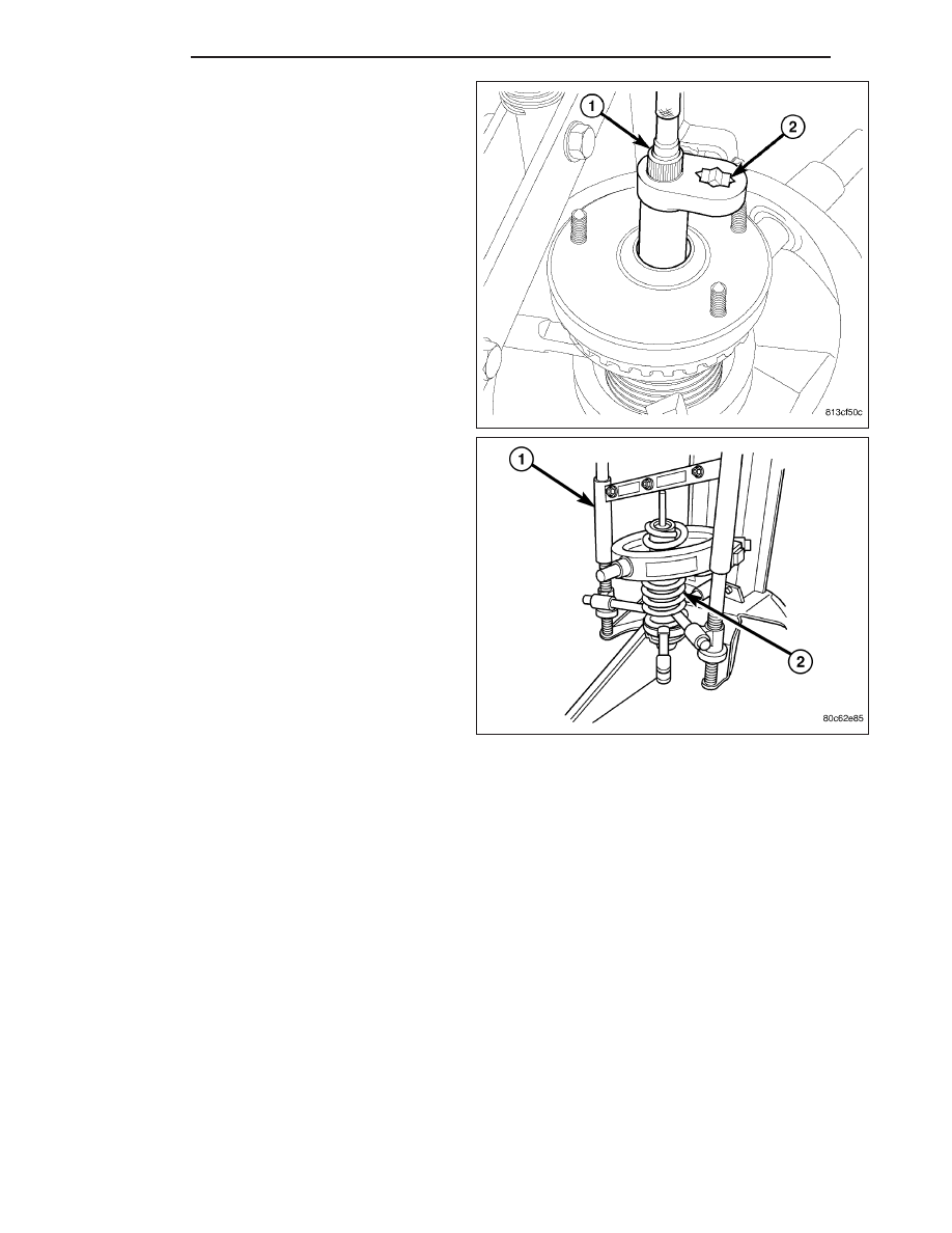
2. Install the shock assembly in the Branick 7200
T
spring removal/installation tool or equivalent (1).
3. Compress the spring (2).
4. Position Wrench (2), Special Tool 9362, on shock
shaft retaining nut. Next, insert 8 mm socket
though Wrench onto hex located on end of shock
shaft. While holding shock shaft from turning,
remove nut from shock shaft using Wrench.
5. Remove the upper shock nut.
6. Remove the shock.
7. Remove the shock upper mounting plate.
8. Remove and inspect the upper and lower spring
isolators.
INSTALLATION
1. Install the lower isolator.
2. Install the upper isolator.
3. Position the shock into the coil spring.
4. Install the upper shock mounting plate.
ND
FRONT
2 - 33
5. Install Wrench (on end of a torque wrench), Special
Tool 9362, on shock shaft retaining nut. Next, insert
8 mm socket though Wrench onto hex located on
end of shock shaft. While holding shock shaft from
turning, tighten nut using Wrench to 90 N·m (66 ft.
lbs.) torque.
6. Install the shock upper mounting nut.
7. Decompress the spring (2).
8. Remove the shock assembly from the spring com-
pressor tool (1).
9. Install the shock assembly (Refer to 2 - SUSPEN-
SION/FRONT/SHOCK - INSTALLATION).
STABILIZER BAR
DESCRIPTION
The bar extends across the front underside of the chassis and connects to the frame crossmember. The ends of the
bar mount to the lower suspension arm. All mounting points of the stabilizer bar are isolated by bushings.
OPERATION
The stabilizer bar is used to minimize vehicle front sway during turns. The bar helps to maintain a flat attitude to the
road surface.
2 - 34
FRONT
ND
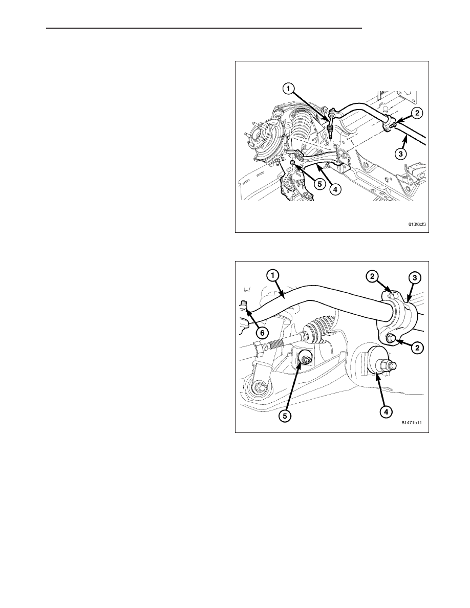
REMOVAL
1. Remove the stabilizer link (1) upper nut and
remove the retainers and grommets (Refer to 2 -
SUSPENSION/FRONT/STABILIZER
LINK
-
REMOVAL).
2. Remove the stabilizer bar retainer bolts (2) also
remove the retainers from the frame sway bar and
remove the bar (3).
3. If necessary, remove the bushings from the stabi-
lizer bar.
INSTALLATION
1. If removed, install the bushings on the stabilizer
bar.
2. Position the stabilizer bar (1) on the frame cross-
member brackets and install the bracket (3) and
bolts (2) finger-tight.
NOTE: Check the alignment of the bar to ensure
there is no interference with the either frame rail
or chassis component. Spacing should be equal
on both sides.
3. Install the stabilizer bar (1) to the stabilizer link and
install the grommets and retainers.
4. Install the nuts (6) to the stabilizer link and tighten
to 169 N·m (125 ft. lbs.) (Refer to 2 - SUSPEN-
SION/FRONT/STABILIZER
LINK
-
INSTALLA-
TION).
5. Tighten the bracket bolts (2) to the frame to 61N·m
(45 ft. lbs.).
ND
FRONT
2 - 35
Нет комментариевНе стесняйтесь поделиться с нами вашим ценным мнением.
Текст