Dodge Dakota (ND). Manual — part 1183
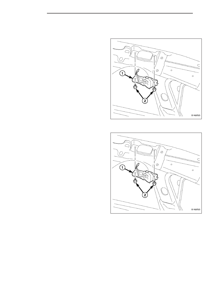
STRIKER-HOOD LATCH
REMOVAL
1. Mark all bolt and striker attachment locations using
a grease pencil or equivalent, to provide reference
marks for installation.
2. Remove mounting bolts and striker (1).
INSTALLATION
1. Install the striker (1), slide back into position and
align all marks.
2. From inside the engine compartment, install the
two bolts (2).
3. Tighten the bolts to 20 N·m (15 ft. lbs.).
23 - 144
HOOD
ND
SUPPORT CYLINDER
REMOVAL
NOTE:
The
hood
support
cylinders
can
be
replaced one at a time.
1. Open and support the hood.
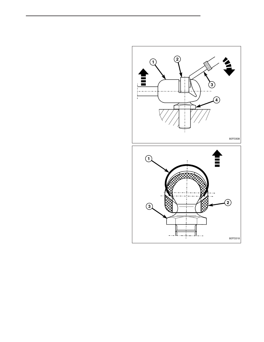
CAUTION: Do not pull on the hood support cylin-
ders at the middle of the support cylinder during
removal. Failure to follow this caution can result in
damage to the hood support cylinders.
2. Using a small flat bladed tool, or equivalent (3),
release the retaining clip (2) at each end of the
support cylinder while carefully pulling the ball
socket (1) away from the ball stud (4).
NOTE: Lift the clips (1) only enough to release the
ball studs (3).
ND
HOOD
23 - 145
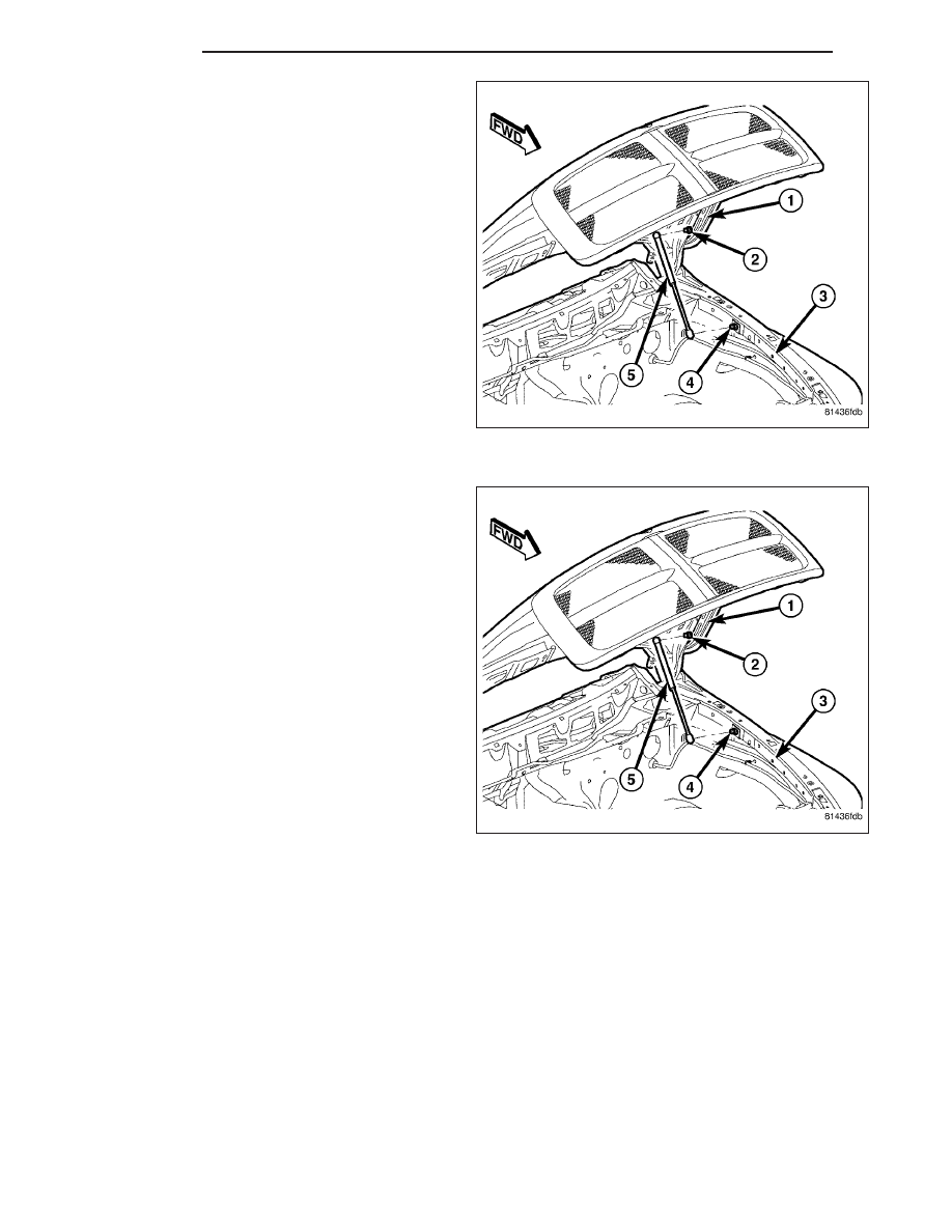
3. Disconnect the hood support cylinder (5) from the
hood (1) and the fender rail (3).
4. If required, remove the upper ball stud (2) from
hood and the lower ball stud (4) from the fender
rail.
INSTALLATION
1. If removed, install the upper ball stud (2) onto the
hood (1) and the lower ball stud (4) onto the fender
rail (3). Install the ball studs securely.
CAUTION: Do not push on the hood support cylin-
ders at the middle of the support cylinder during
installation. Failure to follow this caution can
result in damage to the hood support cylinders.
NOTE: Install the hood support cylinders with the
cylinder end connected to the hood as shown.
NOTE: If required, only release each retaining clip
enough to install the ball socket onto the ball
stud.
2. Install the hood support cylinder (5) over the upper
and lower ball studs and fully engage the retaining
clips.
23 - 146
HOOD
ND
INSTRUMENT PANEL
TABLE OF CONTENTS
page
page
INSTRUMENT PANEL
. . . . . . . . . . . . . . . . . 147
BEZEL-CLUSTER
. . . . . . . . . . . . . . . . . . . . . . . . . . . . 148
. . . . . . . . . . . . . . . . . . . . . . . . 150
GRILLE-DEFROSTER
. . . . . . . . . . . . . . . . . . . . . . . . . . . . 152
. . . . . . . . . . . . . . . . . . . . . . . . 153
GLOVE BOX ASSEMBLY
. . . . . . . . . . . . . . . . . . . . . . . . . . . . 154
. . . . . . . . . . . . . . . . . . . . . . . . 155
ASSEMBLY-INSTRUMENT PANEL
. . . . . . . . . . . . . . . . . . . . . . . . . . . . 155
. . . . . . . . . . . . . . . . . . . . . . . . 164
COVER-STEERING COLUMN OPENING
. . . . . . . . . . . . . . . . . . . . . . . . . . . . 175
. . . . . . . . . . . . . . . . . . . . . . . . 177
BEZEL-CENTER
. . . . . . . . . . . . . . . . . . . . . . . . . . . . 180
. . . . . . . . . . . . . . . . . . . . . . . . 181
INSTRUMENT PANEL
WARNING
RESTRAINT SYSTEM
WARNING: To avoid personal injury or death, during and following any seat belt or child restraint anchor
service, carefully inspect all seat belts, buckles, mounting hardware, retractors, tether straps, and anchors
for proper installation, operation, or damage. Replace any belt that is cut, frayed, or torn. Straighten any
belt that is twisted. Tighten any loose fasteners. Replace any belt that has a damaged or inoperative buckle
or retractor. Replace any belt that has a bent or damaged latch plate or anchor plate. Replace any child
restraint anchor or the unit to which the anchor is integral that has been bent or damaged. Never attempt to
repair a seat belt or child restraint component. Always replace damaged or faulty seat belt and child
restraint components with the correct, new and unused replacement parts listed in the daimlerchrysler
mopar parts catalog.
WARNING: To avoid personal injury or death, on vehicles equipped with airbags, disable the supplemental
restraint system before attempting any steering wheel, steering column, airbag, occupant classification sys-
tem, seat belt tensioner, impact sensor, or instrument panel component diagnosis or service. Disconnect
and isolate the battery negative (ground) cable, then wait two minutes for the system capacitor to discharge
before performing further diagnosis or service. This is the only sure way to disable the supplemental
restraint system. Failure to take the proper precautions could result in accidental airbag deployment.
WARNING: To avoid personal injury or death on vehicles equipped with airbags, before performing any
welding operations disconnect and isolate the battery negative (ground) cable and disconnect all wire har-
ness connectors from the airbag control module (acm). Failure to take the proper precautions could result
in accidental airbag deployment and other possible damage to the supplemental restraint system circuits
and components.
WARNING: To avoid personal injury or death, do not attempt to dismantle an airbag unit or tamper with its
inflator. Do not puncture, incinerate, or bring into contact with electricity. Do not store at temperatures
exceeding 93° c (200° f). An airbag inflator unit may contain sodium azide and potassium nitrate. These
materials are poisonous and extremely flammable. Contact with acid, water, or heavy metals may produce
harmful and irritating gases (sodium hydroxide is formed in the presence of moisture) or combustible com-
pounds. An airbag inflator unit may also contain a gas canister pressurized to over 2500 psi.
ND
INSTRUMENT PANEL
23 - 147
Нет комментариевНе стесняйтесь поделиться с нами вашим ценным мнением.
Текст