Dodge Dakota (ND). Manual — part 1273
B1079–CLIMATE CONTROL COOL DOWN TEST EXCESSIVE TIME
For a complete wiring diagram Refer to Section 8W.
Theory of Operation
The Cooldown Test checks A/C system performance based on Evaporator Temperature Sensor input. The main cri-
teria is to lower evaporator temperature 11.11°C (20°F) within one minute. Before starting the test, the evaporator
temperature must be above 18.3°C (65°F) and the blower speed must be set to high speed. When the test is run-
ning, A/C Select and A/C Request will be on and the A/C status indicator will flash. When the test is complete, the
scan tool will display one or more test status messages to indicate the outcome of the Cooldown Test. A Successful
Cooldown – Test Passed status message indicates that the main test criteria was met. A DTC Set During Routine
– Test Not Passed status message indicates that the A/C system is unable to lower the evaporator temperature
11.11°C (20°F) within one minute. A Conditions Too Cold – Test Not Run status message indicates that the evap-
orator temperature was below 18.3°C (65°F) when starting the Cooldown Test. A Blowers Not On High – Test Not
Run status message indicates that either the blower speed was not set to high speed prior to starting the Cooldown
Test or the blower speed was changed from high speed to another setting after starting the Cooldown test. A Refrig-
erant Temperature Sensor Error status message indicates that a fault occurred with the Evaporator Temperature
Sensor/sensor circuits. A No Results Stored/Test Not Complete status message indicates that the power was cycled
while the test was running.
•
When Monitored:
When the Cooldown Test is executed.
•
Set Condition:
If the A/C system is unable to lower the evaporator temperature 11.11°C (20°F) within one minute.
Possible Causes
EVAPORATOR TEMPERATURE SENSOR CIRCUITS
EVAPORATOR TEMPERATURE SENSOR
OTHER HVAC SYSTEM FAULTS PRESENT SUCH AS INSUFFICIENT REFRIGERANT CHARGE
POWERTRAIN SYSTEM FAULTS PRESENT
Diagnostic Test
1.
CHECK FOR DTCs IN THE A/C HEATER CONTROL MODULE
Turn the ignition on.
With the scan tool, select ECU View.
With the scan tool, select HVAC.
Are any DTCs present in the A/C Heater Control Module?
Yes
>> Diagnose and Repair the DTC(s). Refer to the Table of Contents in this Section for a complete list of
HVAC related symptoms. Run the Cooldown Test again after the repair is complete.
Perform BODY VERIFICATION TEST – VER 1. (Refer to 8 - ELECTRICAL/ELECTRONIC CONTROL
MODULES/FRONT CONTROL MODULE - DIAGNOSIS AND TESTING).
No
>> Go To 2
24 - 90
HVAC - ELECTRICAL DIAGNOSTICS
ND
B1079–CLIMATE CONTROL COOL DOWN TEST EXCESSIVE TIME (CONTINUED)
2.
CHECK FOR DTCs IN THE PCM
With the scan tool, select PCM.
Are any DTCs present in the PCM?
Yes
>> Diagnose and repair the DTC(s). (Refer to 9 - ENGINE - DIAGNOSIS AND TESTING) for PCM DTCs.
Run the Cooldown Test again after the repair is complete.
Perform BODY VERIFICATION TEST – VER 1. (Refer to 8 - ELECTRICAL/ELECTRONIC CONTROL
MODULES/FRONT CONTROL MODULE - DIAGNOSIS AND TESTING).
No
>> Refer to the Service Information for additional Cooldown Test related diagnostic information and testing
procedures. Run the Cooldown Test again after the repair is complete.
Perform BODY VERIFICATION TEST – VER 1. (Refer to 8 - ELECTRICAL/ELECTRONIC CONTROL
MODULES/FRONT CONTROL MODULE - DIAGNOSIS AND TESTING).
ND
HVAC - ELECTRICAL DIAGNOSTICS
24 - 91

B2214–(HVAC) CLIMATE CONTROL INTERNAL
For a complete wiring diagram Refer to Section 8W.
•
When Monitored:
With the ignition on.
•
Set Condition:
If the A/C Heater Control has an internal fault. This DTC has a maturing time of 5 seconds and a de-maturing
time of 10 seconds. If the DTC’s status changes from active to stored it will stay in memory for 100 ignition
cycles.
Possible Causes
A/C HEATER CONTROL
NOTE: This DTC must be active for the results of this test to be valid. Do not perform this test if this DTC
is stored. Refer to HVAC System Test for stored DTC test procedures.
Diagnostic Test
1.
REPLACE THE A/C HEATER CONTROL
Repair
Replace the A/C Heater Control in accordance with the Service Information.
Perform BODY VERIFICATION TEST – VER 1. (Refer to 8 - ELECTRICAL/ELECTRONIC CONTROL
MODULES/FRONT CONTROL MODULE - DIAGNOSIS AND TESTING).
24 - 92
HVAC - ELECTRICAL DIAGNOSTICS
ND
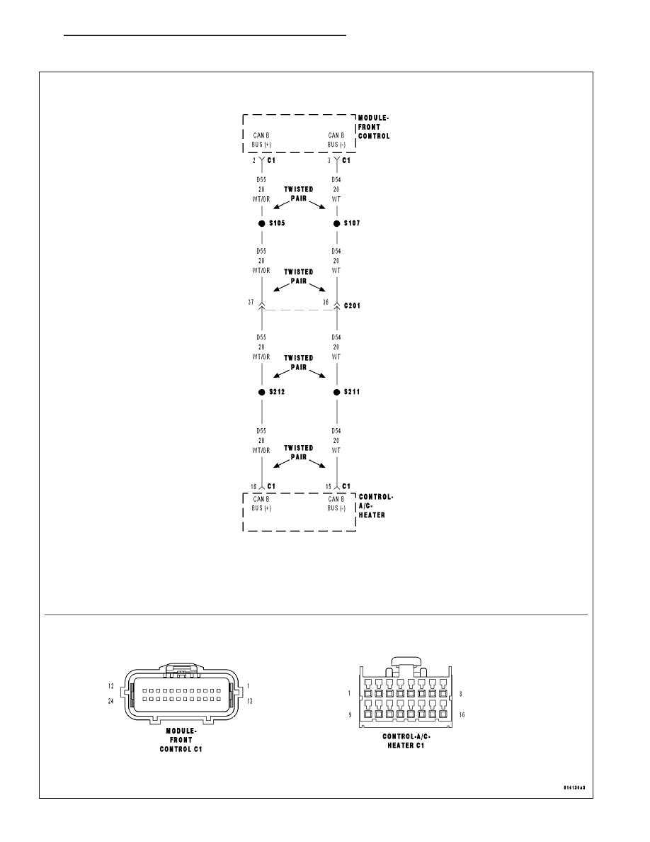
U0019–CAN B BUS
ND
HVAC - ELECTRICAL DIAGNOSTICS
24 - 93
Нет комментариевНе стесняйтесь поделиться с нами вашим ценным мнением.
Текст