Dodge Dakota (ND). Manual — part 1274
U0019–CAN B BUS (CONTINUED)
For the Manual Temperature Control (MTC) circuit diagram (Refer to 24 - HEATING & AIR CONDITIONING - SCHE-
MATICS AND DIAGRAMS).
For a complete wiring diagram Refer to Section 8W.
•
When Monitored:
Continuously
•
Set Condition:
If the CAN B Bus (+) or CAN B Bus (-) circuit is open, shorted to voltage, or shorted to ground.
Possible Causes
ACTIVE U0019 CAN B BUS DTC IN FRONT CONTROL MODULE
(D55) CAN B BUS (+) CIRCUIT OPEN
(D54) CAN B BUS (-) CIRCUIT OPEN
A/C HEATER CONTROL
Diagnostic Test
1.
VERIFY DTC U0019–CAN B BUS IS ACTIVE
Turn the ignition on.
With the scan tool, read HVAC DTCs.
Does the scan tool display active: U0019–CAN B BUS?
Yes
>> Go To 2
No
>> If the DTC is stored, check for an intermittent condition by inspecting the related wiring harness for
chaffed, pierced, pinched, and partially broken wires. Also, inspect the related connectors for broken,
bent, pushed out, spread, corroded, or contaminated terminals.
Perform BODY VERIFICATION TEST – VER 1. (Refer to 8 - ELECTRICAL/ELECTRONIC CONTROL
MODULES/FRONT CONTROL MODULE - DIAGNOSIS AND TESTING).
2.
CHECK FOR ACTIVE CAN B BUS RELATED DTCS IN THE FRONT CONTROL MODULE (FCM)
With the scan tool, read Front Control Module (FCM) DTCs
Does the scan tool display any active CAN B BUS related DTCs?
Yes
>> Diagnose and repair the DTC(s). (Refer to 8 - ELECTRICAL/ELECTRONIC CONTROL MODULES -
DIAGNOSIS AND TESTING).
No
>> Go To 3
24 - 94
HVAC - ELECTRICAL DIAGNOSTICS
ND
U0019–CAN B BUS (CONTINUED)
3.
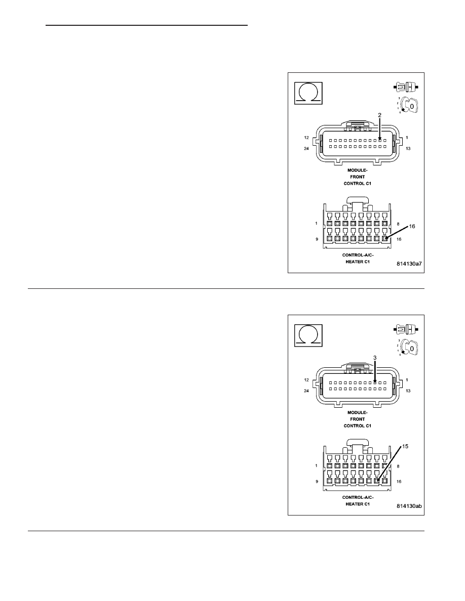
CHECK (D55) CAN B BUS (+) CIRCUIT FOR AN OPEN
Turn the ignition off.
Disconnect the negative battery cable.
Disconnect the A/C Heater Control C1 harness connector.
Disconnect the Front Control Module (FCM) C1 harness connector.
Measure the resistance of the (D55) CAN B Bus (+) circuit between
the Front Control Module C1 harness connector and the A/C Heater
Control C1 harness connector.
Is the resistance below 2.0 ohms?
Yes
>> Go To 4
No
>> Repair the (D55) CAN B Bus (+) circuit for an open.
Perform BODY VERIFICATION TEST - VER 1. (Refer to 8
-
ELECTRICAL/ELECTRONIC
CONTROL
MODULES/
FRONT
CONTROL
MODULE
-
DIAGNOSIS
AND
TESTING).
4.
CHECK (D54) CAN B BUS (–) CIRCUIT FOR AN OPEN
Measure the resistance of the (D54) CAN B Bus (–) circuit between
the Front Control Module C1 connector and the A/C Heater Control C1
harness connector.
Is the resistance below 2.0 ohms?
Yes
>> Replace the A/C Heater Control in accordance with the
Service Information.
Perform BODY VERIFICATION TEST - VER 1. (Refer to 8
-
ELECTRICAL/ELECTRONIC
CONTROL
MODULES/
FRONT CONTROL MODULE - DIAGNOSIS AND TEST-
ING).
No
>> Repair the (D54) CAN B Bus (–) circuit for an open.
Perform BODY VERIFICATION TEST - VER 1. (Refer to 8
-
ELECTRICAL/ELECTRONIC
CONTROL
MODULES/
FRONT
CONTROL
MODULE
-
DIAGNOSIS
AND
TESTING).
ND
HVAC - ELECTRICAL DIAGNOSTICS
24 - 95
U0141–LOST COMMUNICATION WITH FRONT CONTROL MODULE
For the Manual Temperature Control (MTC) circuit diagram (Refer to 24 - HEATING & AIR CONDITIONING - SCHE-
MATICS AND DIAGRAMS).
For a complete wiring diagram Refer to Section 8W.
•
When Monitored:
With the ignition on.
•
Set Condition:
If the A/C Heater Control looses communication with the Front Control Module (FCM). This DTC has a matur-
ing time of 30 seconds and a de-maturing time of 10 seconds. If the DTC’s status changes from active to
stored it will stay in memory for 100 ignition cycles.
(Refer to 8 - ELECTRICAL/ELECTRONIC CONTROL MODULES - DIAGNOSIS AND TESTING) for the diagnostic
test procedure.
24 - 96
HVAC - ELECTRICAL DIAGNOSTICS
ND
U0155–LOST COMMUNICATION WITH CLUSTER/CCN
For the Manual Temperature Control (MTC ) circuit diagram (Refer to 24 - HEATING & AIR CONDITIONING -
SCHEMATICS AND DIAGRAMS).
For a complete wiring diagram Refer to Section 8W.
•
When Monitored:
With the ignition on.
•
Set Condition:
If the A/C Heater Control looses communication with the Cluster (CCN). This DTC has a maturing time of 30
seconds and a de-maturing time of 10 seconds. If the DTC’s status changes from active to stored it will stay
in memory for 100 ignition cycles.
(Refer to 8 - ELECTRICAL/ELECTRONIC CONTROL MODULES - DIAGNOSIS AND TESTING) for the diagnostic
test procedure.
ND
HVAC - ELECTRICAL DIAGNOSTICS
24 - 97
Нет комментариевНе стесняйтесь поделиться с нами вашим ценным мнением.
Текст