Dodge Dakota (ND). Manual — part 827
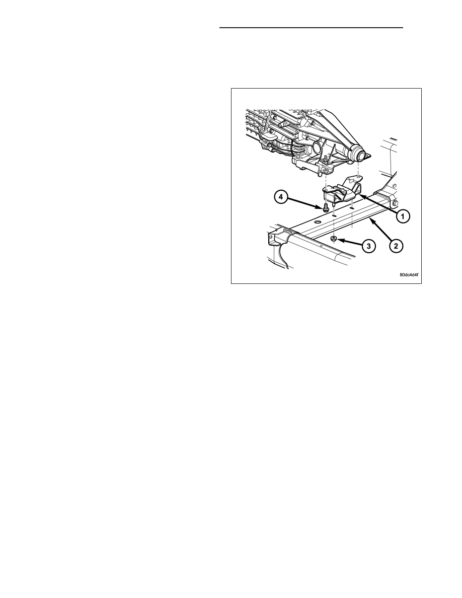
MOUNT - REAR
REMOVAL
1. Raise the vehicle on a hoist.
2. Using a suitable jack, support transmission.
3. Remove the nuts from the transmission mount (1).
4. Remove the two bolts that attach the transmission
mount to the engine bracket.
5. Raise the transmission enough to remove the
mount from the crossmember (2).
6. Remove the mount (1).
INSTALLATION
NOTE: Threadlocking compound must be applied to the bolts before installation.
1. Install the two bolts that attach the transmission mount to the transmission bracket.
2. Torque the bolts to 61N·m (45 ft.lbs.) torque.
3. Lower the transmission so the transmission mount rests on the crossmember, and the studs of the transmission
mount are aligned in the slots in the crossmember.
4. Install the nuts onto the transmission mount studs through the crossmember access slot.
5. Torque the nuts to 54N·m (40 ft. lbs.).
LUBRICATION
DESCRIPTION
The lubrication system is a full flow filtration pressure feed type.
9 - 846
ENGINE - 3.7L SERVICE INFORMATION
ND
OPERATION
Oil from the oil pan is pumped by a gerotor type oil pump directly mounted to the crankshaft nose. Oil pressure is
controlled by a relief valve mounted inside the oil pump housing.
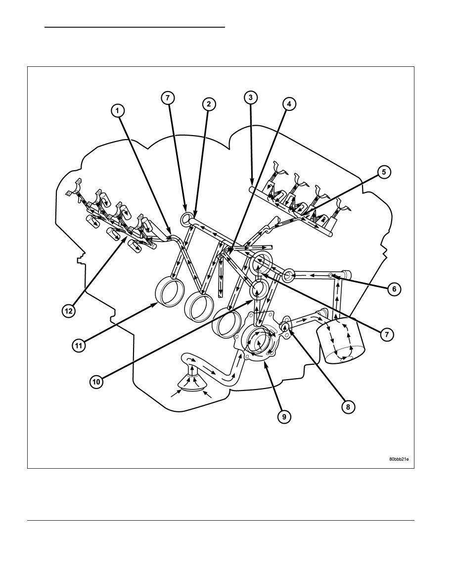
1 - OIL FLOW TO RIGHT CYLINDER HEAD
7 - OIL FLOW TO COUNTER BALANCE SHAFT
2 - CYLINDER BLOCK MAIN OIL GALLERY
8 - OIL PUMP OUTLET TO CYLINDER BLOCK
3 - LEFT CYLINDER HEAD OIL GALLERY
9 - OIL PUMP
4 - OIL FLOW TO BOTH SECONDARY TENSIONERS
10 - OIL FLOW TO CRANKSHAFT MAIN JOURNALS
5 - OIL FLOW TO LEFT CYLINDER HEAD
11 - CRANKSHAFT MAIN BEARING JOURNALS
6 - OIL PRESSURE SENSOR LOCATION
12 - RIGHT CYLINDER HEAD OIL GALLERY
ND
ENGINE - 3.7L SERVICE INFORMATION
9 - 847
The camshaft exhaust valve lobes and rocker arms are lubricated through a small hole in the rocker arm; oil flows
through the lash adjuster then through the rocker arm and onto the camshaft lobe. Due to the orientation of the
rocker arm, the camshaft intake lobes are not lubed in the same manner as the exhaust lobes. The intake lobes are
lubed through internal passages in the camshaft. Oil flows through a bore in the No. 3 camshaft bearing bore, and
as the camshaft turns, a hole in the camshaft aligns with the hole in the camshaft bore allowing engine oil to enter
the camshaft tube. The oil then exits through 1.6mm (0.063 in.) holes drilled into the intake lobes, lubricating the
lobes and the rocker arms.
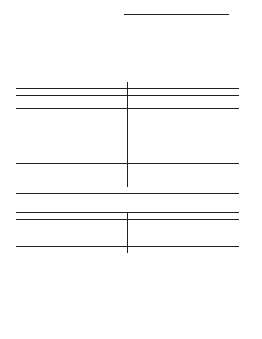
Engine Lubrication Flow Chart - Block: Table 1
FROM
TO
Oil Pickup Tube
Oil Pump
Oil Pump
Oil Filter
Oil Filter
Block Main Oil Gallery
Block Main Oil Gallery
1. Crankshaft Main Journal
2. Left Cylinder Head*
3. Right Cylinder Head*
4. Counterbalance Shaft Rear Journal
Crankshaft Main Journals
Crankshaft Rod Journals
Crankshaft Number One Main Journal
1. Front Timing Chain Idler Shaft
2. Counterbalance Shaft - Front Journal
3. Both Secondary Chain Tensioners
Left Cylinder Head
Refer to Engine Lubrication Flow Chart - Cylinder
Heads: Table 2
Right Cylinder Head
Refer to Engine Lubrication Flow Chart - Cylinder
Heads: Table 2
* The cylinder head gaskets have an oil restricter to control oil flow to the cylinder heads
Engine Lubrication Flow Chart - Cylinder Heads: Table 2
FROM
TO
Cylinder Head Oil Port (in bolt hole)
Diagonal Cross Drilling to Main Oil Gallery
Main Oil Gallery (drilled through head from rear to front)
1. Base of Camshaft Towers
2. Lash Adjuster Towers
Base of Camshaft Towers
Vertical Drilling Through Tower to Camshaft Bearings**
Lash Adjuster Towers
Diagonal Drillings to Hydraulic Lash Adjuster Pockets
** The number three camshaft bearing journal feeds oil into the hollow camshaft tubes. Oil is routed to the intake
lobes, which have oil passages drilled into them to lubricate the rocker arms.
DIAGNOSIS AND TESTING
ENGINE OIL LEAK
Begin with a thorough visual inspection of the engine, particularly at the area of the suspected leak. If an oil leak
source is not readily identifiable, the following steps should be followed:
1. Do not clean or degrease the engine at this time because some solvents may cause rubber to swell, temporarily
stopping the leak.
2. Add an oil soluble dye (use as recommended by manufacturer). Start the engine and let idle for approximately 15
minutes. Check the oil dipstick to make sure the dye is thoroughly mixed as indicated with a bright yellow color
under a black light.
9 - 848
ENGINE - 3.7L SERVICE INFORMATION
ND
3. Using a black light, inspect the entire engine for fluorescent dye, particularly at the suspected area of oil leak. If
the oil leak is found and identified, repair per service manual instructions.
4. If dye is not observed, drive the vehicle at various speeds for approximately 24 km (15 miles), and repeat inspec-
tion.If the oil leak source is not positively identified at this time, proceed with the air leak detection test method.
Air Leak Detection Test Method
1. Disconnect the breather cap to air cleaner hose at the breather cap end. Cap or plug breather cap nipple.
2. Remove the PCV valve from the cylinder head cover. Cap or plug the PCV valve grommet.
3. Attach an air hose with pressure gauge and regulator to the dipstick tube.
CAUTION: Do not subject the engine assembly to more than 20.6 kPa (3 PSI) of test pressure.
4. Gradually apply air pressure from 1 psi to 2.5 psi maximum while applying soapy water at the suspected source.
Adjust the regulator to the suitable test pressure that provide the best bubbles which will pinpoint the leak
source. If the oil leak is detected and identified, repair per service manual procedures.
5. If the leakage occurs at the rear oil seal area, refer to the section, Inspection for Rear Seal Area Leak.
6. If no leaks are detected, turn off the air supply and remove the air hose and all plugs and caps. Install the PCV
valve and breather cap hose.
7. Clean the oil off the suspect oil leak area using a suitable solvent. Drive the vehicle at various speeds approx-
imately 24 km (15 miles). Inspect the engine for signs of an oil leak by using a black light.
INSPECTION FOR REAR SEAL AREA LEAKS
Since it is sometimes difficult to determine the source of an oil leak in the rear seal area of the engine, a more
involved inspection is necessary. The following steps should be followed to help pinpoint the source of the leak.
If the leakage occurs at the crankshaft rear oil seal area:
1. Disconnect the battery.
2. Raise the vehicle.
3. Remove torque converter or clutch housing cover and inspect rear of block for evidence of oil. Use a black light
to check for the oil leak:
a. Circular spray pattern generally indicates seal leakage or crankshaft damage.
b. Where leakage tends to run straight down, possible causes are a porous block, distributor seal, camshaft
bore cup plugs oil galley pipe plugs, oil filter runoff, and main bearing cap to cylinder block mating surfaces.
4. If no leaks are detected, pressurize the crankcase as outlined in the, Inspection (Engine oil Leaks in general)
CAUTION: Do not exceed 20.6 kPa (3 psi).
5. If the leak is not detected, very slowly turn the crankshaft and watch for leakage. If a leak is detected between
the crankshaft and seal while slowly turning the crankshaft, it is possible the crankshaft seal surface is damaged.
The seal area on the crankshaft could have minor nicks or scratches that can be polished out with emery cloth.
CAUTION: Use extreme caution when crankshaft polishing is necessary to remove minor nicks and
scratches. The crankshaft seal flange is especially machined to complement the function of the rear oil seal.
6. For bubbles that remain steady with shaft rotation, no further inspection can be done until disassembled.
ND
ENGINE - 3.7L SERVICE INFORMATION
9 - 849
Нет комментариевНе стесняйтесь поделиться с нами вашим ценным мнением.
Текст